

This post covers the exterior lighting modifications made to my 2008 Alfa Romeo 159 TI. If you are interested in the interior LED conversion guide, click here. This modification can be completed as a single project or as a series of smaller projects as the cost of components is still quite high due to some of the LED types in use. If you do choose to split the project I would suggest separating the turn signals / Indicators, Numberplate lights, sidelights and rear clusters into stand alone projects.

For an alternative approach to upgrade the “Third Brake Light” at position 9, click here to see the Cylon Project.
Each topic area is collapsed below for your ease of navigation so either “Show All” or Expand each sub-topic as needed:
The parts you need for this conversion are as follows:
- 4 x Type 380 (1157) RED 13-LED Superlux [BAY15D,380,1157,P21/5w] 12v (Positions 5,6,7&8)
- 1 x Type 382 CREE Q5 12V/24V HIGH POWER LED BULB for the reverse light (Position 8 )
- 1 x Type 382/P21W 5W CREE Q5 RED LED BULB for the fog light (Position 6)
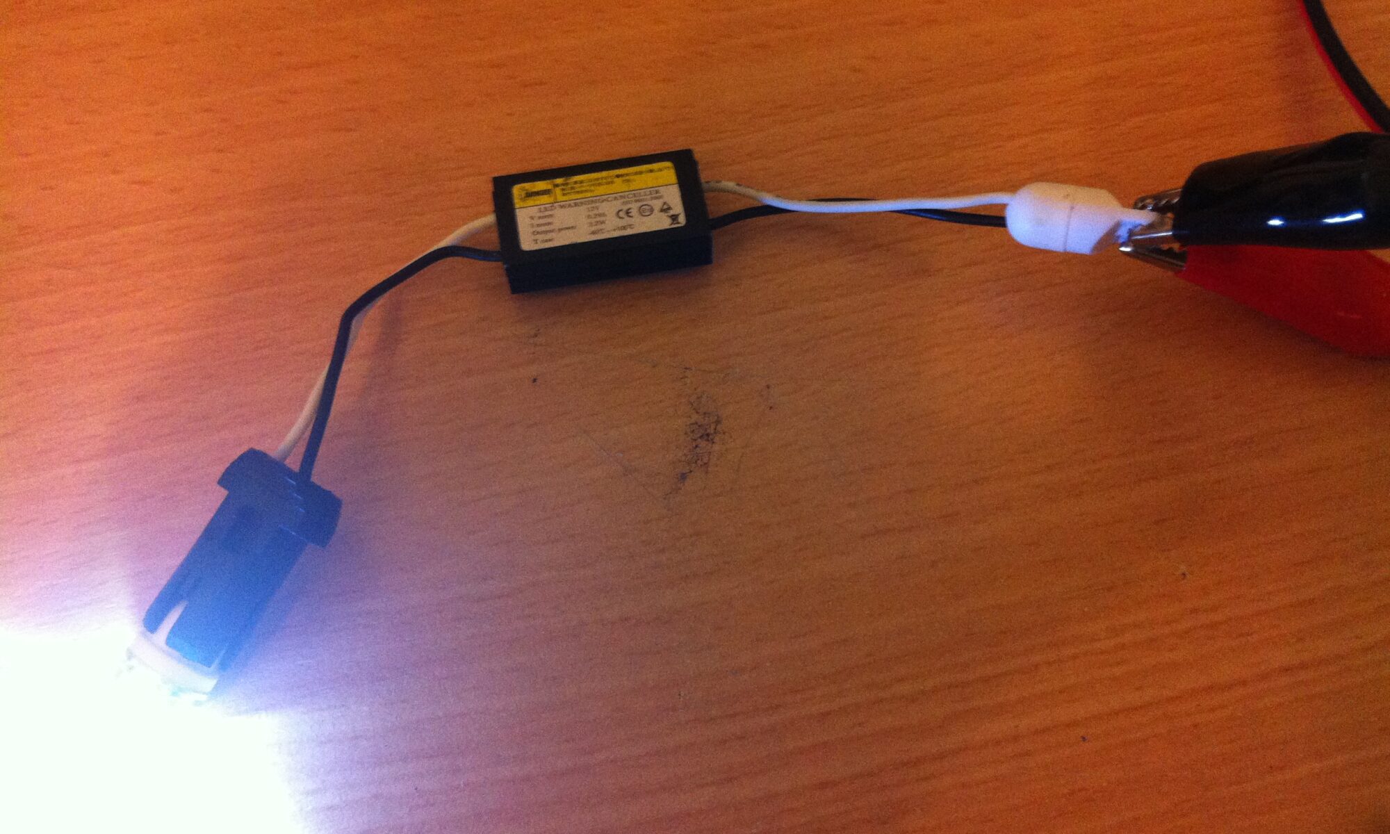
- 2 x CANBUS Type 501/W5W/T10 24 LED Bulbs for the front side lights (Positions 1&2)
- 2 x CANBUS Type 501/W5W/T10 4 LED Bulbs for the numberplate lights (Position 10 )
- 4 x BAU15s 7507 Q5+12SMD=7W Brake/Signal Light 150° LED Bulbs Amber/Yellow PY21W for the front and rear indicators (Positions 1,2,5&7)
- 2 x 5 SMD LED AMBER ORANGE INDICATOR SIGNAL TURNING SIDE LIGHT BULB T10 W5W 501 for the side repeaters (Positions 3&4)
- 11 x 50w 10 ohm Aluminium clad wire wound resistors
- 2 x 25w 47 ohm Aluminium clad wire wound resistors
- 2 x 330 ohm 0.6w metal resistors
- Lots of wire & plenty of heat shrink wrap
- 10 x Red Scotch clips
- 8 x Red 3mm male spade terminals
- 8 x Red 3mm female spade terminals
Estimated Cost: £170-200
Required Tools:
- Soldering iron
- Solder
- Flux paste
- Helping hands
- Hot glue gun
Pro-Tip: You can remove the need to solder as well as reduce the overall effort if your prepared to increase your spend to buy the resistors pre-made from ebay. The example increase is DIY=£2 for a pair, whereas on ebay that would be £7-10 for the pair.
“CAN Bus”
Most modern cars make use of numerous computers within the vehicle all connected through something known as a Controller Area Network or “CAN Bus” for short. One of these computers is typically dedicated to looking after the internal electronics such as dials and gauges etc as well as the lighting circuits, in the Alfa its called the “Bodywork Computer” or “NBC” and one of its jobs is to make sure that if a bulb blows, you are warned when you get into the car with a friendly picture of your car and a warning symbol showing you which bulb has blown. This is a great feature, but unfortunately, it works against you when your swapping a traditional filament bulb for a new style LED replacement. The reason why is that a traditional bulb illuminates by putting a voltage across a metal element, essentially shorting out the circuit, causing it to heat up and emit light. This process creates a reasonably high load, measured in amps. LED bulbs work completely differently, essentially, they produce light by pushing electrons around inside a solid semi-conductor, which is a much more efficient process that creates significantly less load. This is where the problem comes! The bodywork computer puts a small amount of electricity on the bulb circuit to test that it has a connection and that the filament has not blown, so when you swap your old filament bulb for a LED one, you get one or two issues. The first issue is that the bodywork computer thinks the bulb has blown and lets you know, the second is that the small amount of power used to perform the test is actually enough to gently illuminate the LED, so it always stays on and never switches off, even when the ignition is off!
In order to fix this issue you need to use more power than you need to actually run the LED so you need to add resistance to the circuit to absorb and use extra power and simulate load. Exactly how much resistance you need is a mathematical calculation known as “ohms law” which takes a number of variables and tells you how much resistance, measured in ohms, you need to add. When you add resistance to a circuit it creates heat as the excess power is turned into heat energy to be dissipated. For this reason its important to make use of a large wattage resistor (wattage is the measure of a resistors heat dissipation ability) so that you don’t either burn out the component or even worse, create a fire hazard.
For each of the bulbs I have used, I have first measured the amps that the original filament bulb runs at, and then the amps that the replacement LED runs at to determine the correct resistor to add. For most of my replacement LEDs I have needed to simulate around 1.2amps of additional load, which was achieved using a 50w, 10 ohm aluminium wire wound resistor, however for the two side repeaters I only needed to simulate around 0.3 amps, so I used a 47 ohm, 25w aluminium wire wound resistor. In this case, because the ohms was higher and the load to simulate was lower, I was able to use a smaller wattage which reduced the actual size of the resistor.
As a point of note, every bulb in the 159 except the reverse light and the third brake light, has a CAN-BUS sensing circuit on it, and as such, will need to be replaced with a CAN-BUS capable LED or have additional resitors added to that circuit.
Front Clusters
The front clusters can be quite difficult to work with as, depending on your engine, there may not be much room to work. As mine is the 2.4 JTDM engine, I have the least amount of room so small hands, patients and a high tolerance for pain are required. The 24LED sidelights require a small modification to them before they are installed as, despite being sold as “CAN Bus friendly”, they do not simulate enough load for the Alfa to be happy with, as such, additional load, all be it a very small amount, is required. The modification requires the addition of a 330 ohm 0.6w resistor to each bulb so that when it is installed, the computer is happy that the bulb is not blown. I achieved this by soldering the LED directly onto the bulb as per the following images. Once the bulbs are ready to be installed, the next job is to prepare two of the 10 ohm 50w resistors for the front indicators. This is done by soldering around 6-8 inches of wire onto either terminal of the resistors, heat shrinking the exposed connections, and then putting scotch blocks on the end, ready to be attached to the wires inside the headlight.


The installation process is fiddly and generally very annoying but essentially for the sidelight, follow the eLearn guide below:

For the indicator, the following eLearn guide shows you how to change the bulb, however, in addition to this, you need to scotch clip the resistor to the two wires connecting to the bulb holder and place it somewhere inside the light unit once complete. In general I use a heat transfer sticky pad to affix the resistor to a suitable surface to stop it moving around:

Rear Clusters
The rear clusters are by far the most involved and require the most effort. They are split into two sections per side, one fixed to each wing (Potions 5&7) and two fixed to the boot lid (Positions 6&8). As each light unit contains a number of bulbs to replace its easier to make a “loom extension” that sits in between the original connector and the light unit and adds in the extra resistors in bulk for the bulbs. As such the light units at Positions 5 & 7 require 3 x 10 ohm , 50 w, aluminium wire wound resistors each, while the light unit at Position 6 requires 2 x10 ohm , 50 w, aluminium wire wound resistors and the light unit at Position 8 only requires 1 x10 ohm, 50 w, aluminium wire wound resistor.
For Position 8 it is easier to just scotch clip a single resistor into place over the “tail light” connection, as this is the only live circuit that makes use of a CAN Bus check signal. The Reverse Light does not have any CAN Bus checking (we will assume because you would notice!), and despite the type 1159 dual element stop/tail bulb being used in this position, only the tail element is wired up. I assume this was a “design feature” to save you carrying two different bulb types for the rear, although I find it quite stupid personally. Position 8 wiring is illustrated below:

Position 6 requires two resistors installing and as such its easier to build an extension for that connector than actually scotch clip them in place. The extension looks like the following and is attached to the shell of the car using heat transfer sticky pads for optimum heat dissipation into the vehicles shell:


These rear clusters are accessed for this upgrade as per the following guide:

Positions 5 & 7 are both the same with a three resistor unit required. The following images show the unit and the installation:


Whenever I have installed a loom extension I have coated the connections in hot glue so that they cannot come loose during driving conditions and I have used the sticky pads to secure the resistors on top of the metal surround for the light unit for optimal heat dissipation into the body shell..
The bulbs and loom extensions are then installed through the normal bulb change procedure:

Side Repeaters
The side repeaters have a limited amount of space to accommodate a bulb and as such the overall size of the bulb is an important factor. The chosen bulb is as large as the unit can house and also makes use of a multi-SMD architecture to provide a good directional light output. Aside from changing the bulb, additional resistance is needed to simulate the missing load of the original bulb. These resistors can be mounted in the engine bay, and cables run through the wing to join up with the side repeaters, where they can be scotch clipped to the existing wiring and then covered in ample amounts of insulation tape to avoid any moisture getting into the joins:
")


I used heat transfer sticky pads to stick the resistors to the top of the suspension pillars and ran the cable through the seem at the top of the wing down through to the side repeater hole for ease. This was a remarkably easy process and required only limited “fishing” for the cable.
Removal of the side repeater is a very simple process as per the following eLearn guide:

Number Plate Lights
The number plate LEDs are a simple swap of the original W5W type bulbs for the 4 LED versions. The 4 LED versions have been chosen for two primary reasons, firstly, I do not want it to be brighter than the original bulbs and secondly, the bulb housing do not have any built in reflectors, so its important to have the LEDs pointing the right way. The chosen bulbs satisfy these criteria well and provide a good light output. The upgrade is simple and the eLearn guide is below:

The finished product looks like this:


Third Brake Light
The third brake light employs a 10 x filament bulb light bar plugged into the back of the reflector unit, so to complete the LED conversion this is going to need to change. To do this, you will need to make a replacement bulb as no “off the shelf” direct replacements exist. I have built one called “The Cylon” which runs each LED individually and has some cool effects, but if you just want a simple LED replacement you can try the following approach. (warning, I have not done this so it needs verifying).
You will need to get 10 x 5mm round high power red LEDs with as wide a viewing angle as possible, like these, but do your own research to find the best ones you can. Once you have your LEDs you can use an on-line LED wizard to figure out the best way of wiring them up and what resistance you need to add. This will give you an output like this:

All you then need to do is remove the third brake light from the car, get out your soldering iron and hot glue your LEDs directly into the back of the reflector:


Once the glue is dry, make the connections as shown in the diagram, solder up all the parts and run about 18 inches of cable from the new unit to a “2 pin header row” that can be used to make a plug:


The completed unit can then be installed back into the car. There is no CAN Bus issues on this circuit so the light will just work like the original.

The complete/finished product is better displayed as a video and as such you can watch this one I made of the complete conversion: