Please note, Project Halo is now being continued by Chris & Samir over on the facebook page. I no longer supply controllers.
Project Halo started as a concept to integrate BMW Angel eye style DRLs into the 159/Brera/Spider triple headlight configuration. Initial development work was completed by myself & YonasH. YonasH pioneered the first sets of Halo’s in a kit form that could be bought and installed as a DIY solution, however both of our efforts to disassemble the headlights resulted in failure or breakage and the only viable solution was to cut the lenses off, install the rings and glue the lenses back on.
As this was not a viable option, development ceased for around a year before starting up again after discussions with Coxy1 on headlight disassembly. Coxy1 was able to pioneer an approach to taking the headlights apart, but only if they were new ones where the glue had not yet had time to cure fully (several years of use on a car cures them fully!!)
Once this had been solved, I restarted development on the electronic controllers for the headlights to meet UK specifications and simplify the amount of electronics & wiring needed in comparison to the approach YonasH took.
This site serves as the primary location for all documentation resources related to the project for those that want to join in the fun!
The projects history is documented on Alfaowner.com
The Project now has an active Facebook Page where we will track interest in controller batches. Please join the page and let us know if you would like a set of controllers for your project:
There are guides available to help with the DIY on my site, see the following links:
- Headlight Splitting
- Headlight Wiring
- Installation of the Rings
- Power Supplies
- Bumper Removal
- Make your own 12V 10s off Relay
Overview & Prerequisites
It is technically possible to utilise these controllers on any vehicle that has after market DRLs. This is with the caveat that the DRL’s being driven can be measured for there voltage and amperage requirements so that the controllers can be configured accordingly. Where the DRL’s are the same ring type as those the units were designed for this is not required.
Vehicles
Alfa Romeo 159/Brera/Spider
The original design of these units is for the following vehicles:
- Alfa Romeo 159
- Alfa Romeo Brera
- Alfa Romeo Spider
These three vehicles all utilise the same triple circular headlight design requiring 3 different sized rings per headlight:
- 85mm
- 90mm
- 95mm
Parts List
Power Supply Parts
The following parts are required to power the Halo’s:
| Item | Unit Cost | QTY | Total | Supplier | What it does? |
|---|---|---|---|---|---|
| Durite 12v 10s delay off relay | £50 | 1 | £50 | Auto-Electrical Specialist | Provides continious operation while engine starts |
| DC/DC Converter PSU | £16.90 | 1 | £16.90 | Ebay | Supplies clean regulated power to the system |
| Superseal connector 2 pin female (pack of 5) | £2.22 | 1 | £2.22 | Ebay | Connection from headlight to PSU |
| 12v twin core 3A wire (5m) | £2.49 | 1 | £2.49 | Ebay | For connections inside headlights |
| 12v twin core 6A wire (2m) | £1.45 | 1 | £1.45 | Ebay | For connections from PSU to headlights |
| 5 x Mini Blade fuse Holder | £4.99 | 1 | £4.99 | Ebay | For safety! |
| Mini blade fuse (5A x 10) | £1.00 | 1 | £1.00 | Ebay | get it anywhere! |
| Mini blade fuse (2A x 10) | £1.00 | 1 | £1.00 | Ebay | get it anywhere! |
Item 1 above (12v 10s delay off relay) could be replaced with a simple 12v relay if the need for the rings to stay lit during the engine crank is not required. This would reduce the cost of that part to around £5.
Halo Parts
The actual Halo’s require the following parts:
| Item | Unit Cost | QTY | Total | Supplier | What it does? |
|---|---|---|---|---|---|
| CST100 Gold Plated Crimp Contact | £15.25 | 1 | £15.25 | http://uk.rs-online.com/ | packs of 50 only! Makes 25 connectors RS Part number: 293-0098 |
| 2 way Scoket Housing 2.54mm pitch | £0.76 | 2 | £1.52 | http://uk.rs-online.com/ | packs of 10. RS Part number: 293-0026 |
| Mixed Heat Shrink Pack | £6.89 | 1 | £6.89 | Ebay | For Electrical Connections |
| DRL Controller Module | £50.00 | 2 | £100.00 | http://jabawoki.com/ | Creates the magic! |
| 85mm ring | £11.00 | 1 | £11.00 | www.ebay.co.uk | Shiny things |
| 90mm ring | £11.00 | 1 | £11.00 | www.ebay.co.uk | Shiny things |
| 95mm ring | £11.00 | 1 | £11.00 | www.ebay.co.uk | Shiny things |
Make sure when you order the rings you specify the right colour. The “white” ones are a perfect match for HIDs at about 5500K whereas the “Cold White” ones have an electric blue hint that makes them closer to 7000K. The adjacent image shows the difference quite well. Also, with regard to rings its very important they are exactly the type I list. Other style rings may not work and may damage the controllers.
The DRL Controller Modules are available direct from myself.
Optional Parts
Although technically optional it is highly recommended that you buy 2 new headlights to work on. This is because the OE headlights use a glue that is near impossible to melt. It also provides you ample time to work with the headlights off the car and not leave your car in a state unfit to drive. Bear in mind you can always sell your OE headlights to someone else to get some of this cost back!
| Item | Unit Cost | QTY | Total | Supplier | What it does? |
|---|---|---|---|---|---|
| Set of Headlights | £158.00 | 1 | £158.00 | www.ebay.co.uk | Provides something to work with |
Make sure you order the right headlights! there is a difference between LHD and RHD units. Also different makes exist, Lucas or Depo are most common. I have Depo lights on mine and I don’t like them. They are clearly a lesser quality and I have had issues with the adjustable motors to raise and lower the light beam stripping the cogs. Others have Depo lights with no issues so it could just be the amount of abuse I have given them during development!
DRL Controller Information
Modes of Operation
The controllers have been designed to meet the same requirements and operation of any UK specification OE fitted DRL unit. As such they intelligently determine their required mode from the specific function the headlight is performing at any given time.
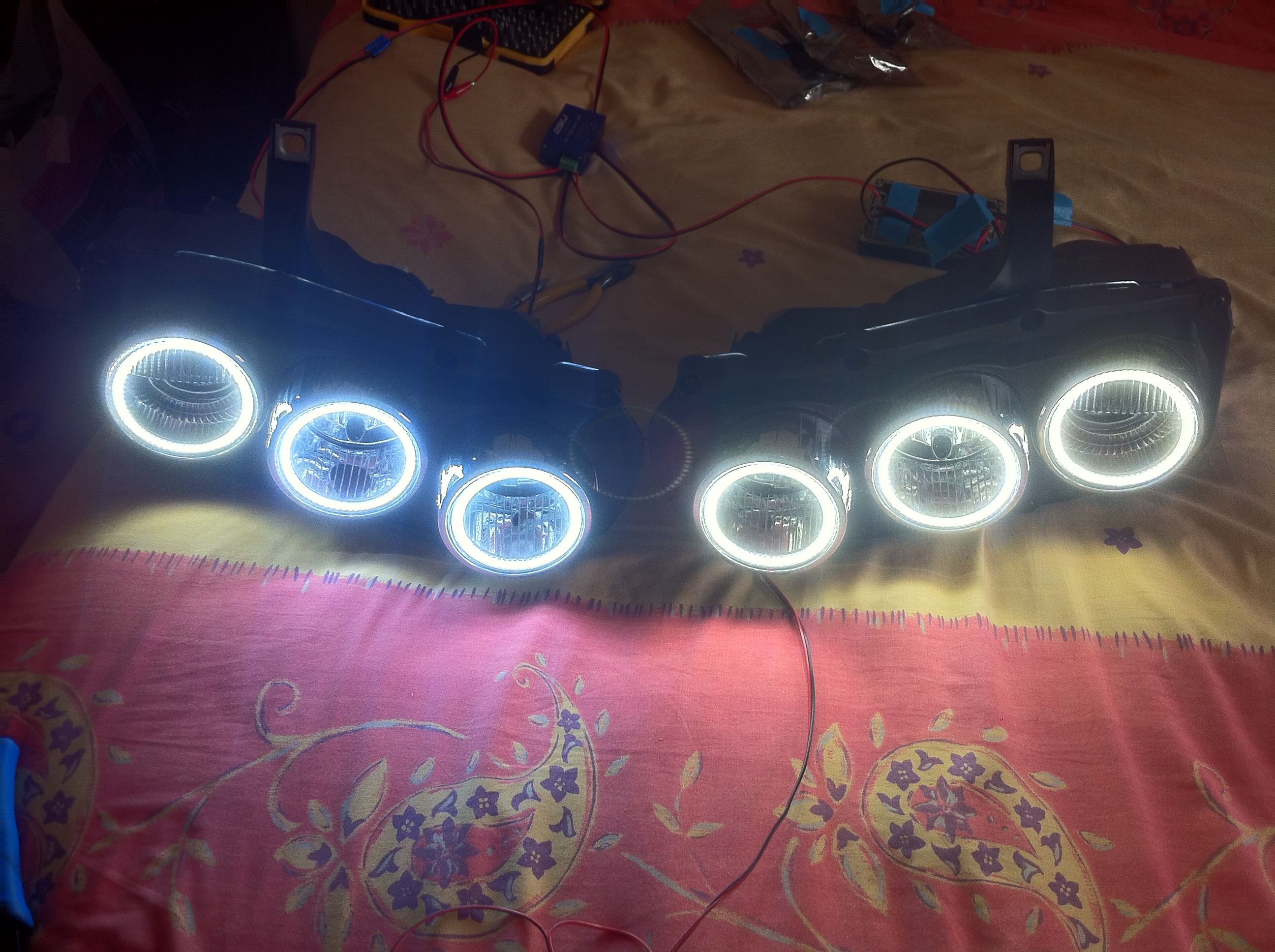
The first mode of operation is the start-up routine. It is the first portion of code that is run when the controllers are powered up. This routine lights each ring in sequence from 0% to 100% and back to about 80% from the inside ring to the outside creating a staged power on effect.
By default, the unit will run all 3 rings at about 80% intensity, this mode is selected by virtue of no lights being switched on, i.e “Daylight” mode.
When it becomes dark and you switch on your headlights (or the automatic headlight function does this for you, should your car have that feature), the controllers will detect that the driving lights are on and dim the rings to about 60% brightness for night time operation.
If main/high beam is engaged all the rings will be switched to full power 100% intensity for the period the main/high beam is active to provide maximum light from the front of the vehicle.
The final and most important mode of operation is engaged when the indicators are activated. When the indicator is sensed as on within the headlight, the controller will override all previous modes and switch the two outer rings to 50% while the inner ring is switched off so that the indicator can be easily seen. Regardless of what mode the DRLs are in, when the indicator is active this mode overrides it for safety.
As the logic for the indicator mode uses the same voltage sensing approach as the other modes due to the fact that indicators flash, their is a small 400ms delay built into the logic of the sensing so that the mode does not constantly change while the indicator is flashing. This way the mode stays active until the indicator use has stopped at which point it returns to the previously selected mode.
Any less than 400ms results in occasional bounces between modes so is the safest duration.
How modes are selected
When +12v is applied to the specific bulb in the headlight, a set of jumper wires from that bulb feed to one of the controllers inputs where the voltage is detected by the Micro-Controller and the mode changed. The controller makes use of an opto-isolator circuit to protect the sensitive micro-controller inputs from the potentially harmful transient voltage of the bulb feeds for added longevity and protection.
The following bulbs / feeds are monitored in each individual headlight:
- Driving Lights
- Main Beam
- Indicator
Controller Hardware
The controller hardware is entirely custom designed by JabawokJayUK with the help and support of RC.
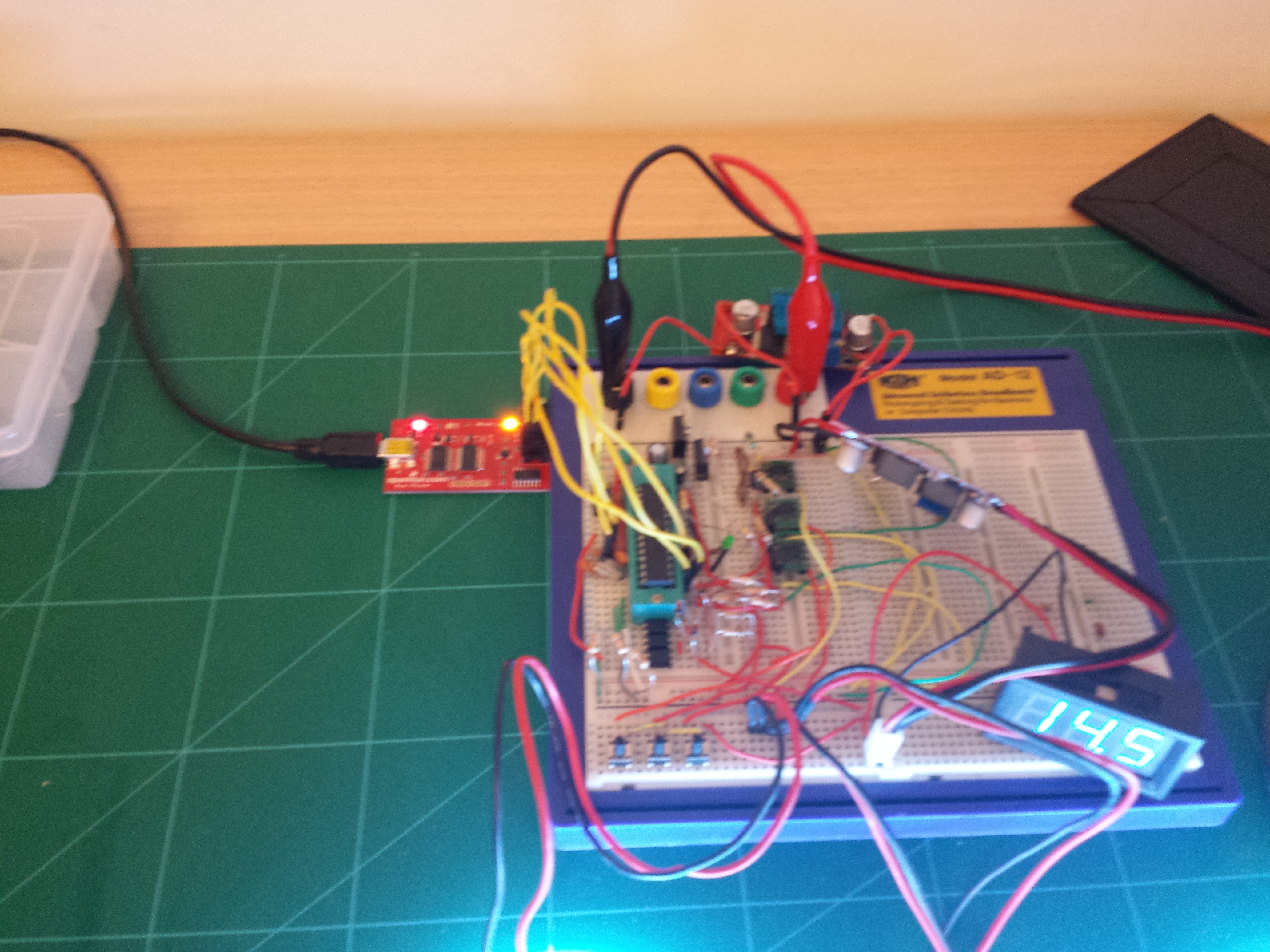
Pre Alpha
The initial incarnation of the project and test bed for code etc is a breadboard based arduino platform. This is where all the design and R&D happened.
Version 1
The first generation controller utilised a through hole design for ease of prototyping and short run assembly.
Although every care was taken in the design of these units it was deemed that the mass market resale of them would be problematic due to the time taken to assemble them combined with the long term effects of solder joints becoming worn. As a result these units only exist in three cars and will eventually be replaced with the Version 2 hardware.
Version 2
The second generation of the hardware was designed entirely by “Xeropage”. A fellow electronics junkie and security industry player. My schematic was taken, adapted and migrated into a fully surface mount design that will stand the test of time. All components in this design are “automotive grade” which means they are able to stand up to greater cold and heat variations and are better suited to working in the harsh environment of a car.
Version 2 further expanded on the initial design to add an extra +12v trigger input and an extra ring output. These additional features served to make the unit more flexible for target vehicles other than the 159/Brera/Spider models it was designed for. Most vehicles have a need for 2 or 4 rings, rather than the 6 needed for the 159/Brera/Spider, so the additional output & input meant a single controller could drive 4 rings and take main beam, driving lights & 2 x indicator triggers.
The additional input also adds value to the 159/Brera/Spider as it can be used to sense the ignition +12v feed. When combined with a “timed off” relay that continues to power the units after the ignition has switched off, the controllers can tell that the power is about to go and run a “power off” routine before it does.
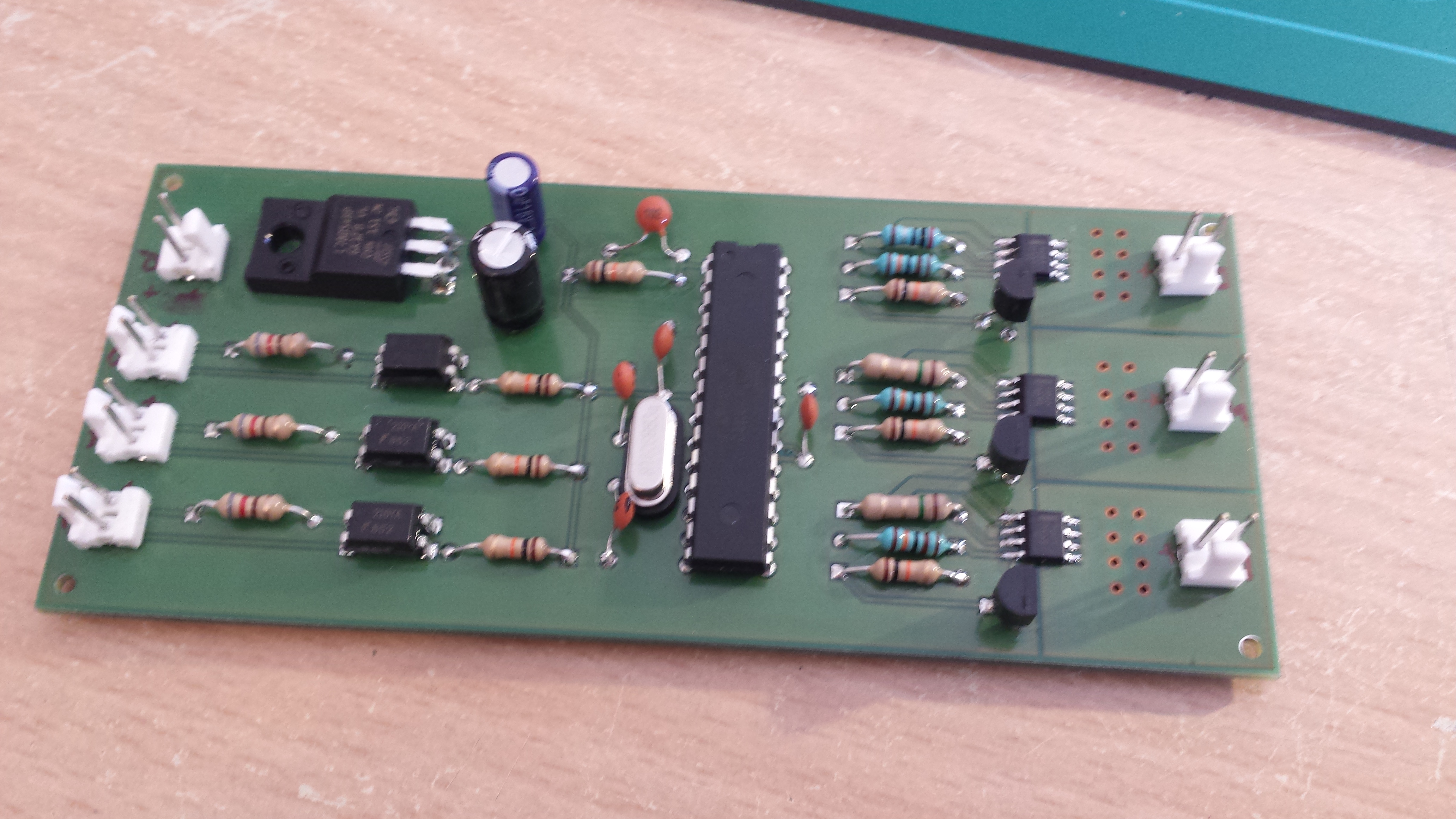
Version 2.1
This is the first version of controller that was shipped to market and has only minor differences to version 2 above. They are easily identifiable as having a green circuit board:

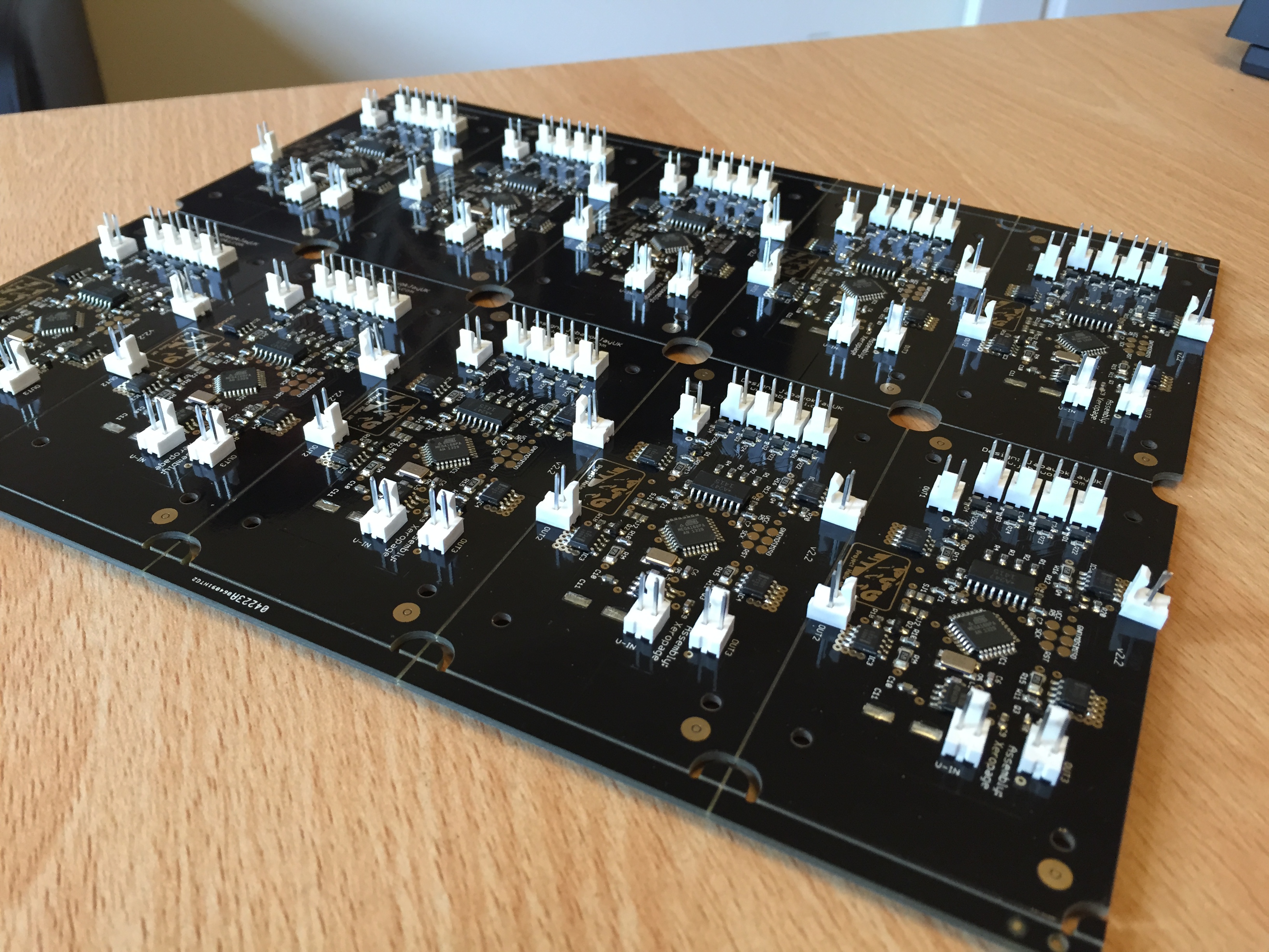
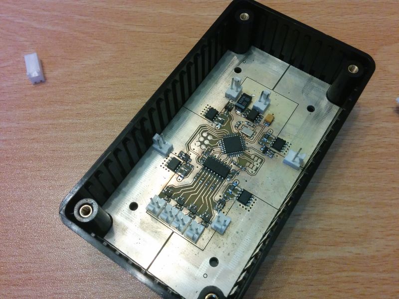
Version 2.2
This generation of controller had some improvements made to the components in terms of voltage capacity to help protect against shorts and over-voltage situations and also changed PCB suppliers and style to a better quality gold plated one. These boards are black so easily identifiable as version 2.2:
Version 2.2 boards are not compatible with V2.1 wiring. There is a polarity change on these boards that means they are not a direct swap for V2.1.