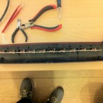
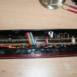
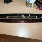
Why did I do this?
Take a look, that’s why!
Ok, so now I know you want one! If you do, they can be made to order.
Background
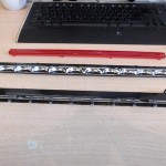
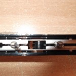
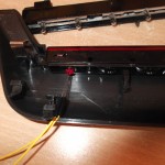
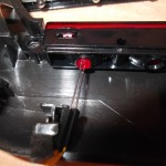
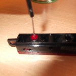
Its probably worth recapping as to why this project came about. Essentially, whilst on a mission to replace every bulb in my car with a LED version, I stumbled across the fact that my high level brake light was not LED as you would typically expect, but instead had a strange row of bulbs on a common rail power system that clipped into the back of the reflector housing:
This was not ideal and lead me to need to replace it. An initial investigation showed me that it would be very simple to replace the bar with a row of LEDs hot glued into place and powered from the +12 feed into the unit, but after some initial consideration I thought it might be more interesting to be able to run each LED individually and control the sequencing etc. for some special effects.
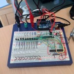
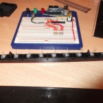
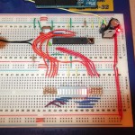
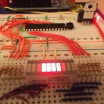
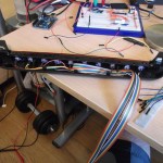
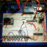
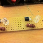
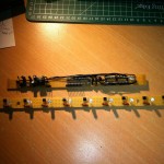
Aside from the need to upgrade the unit, the primary reason behind going down the Arduino route was an excuse to really get my head around the ATMega and micro-controllers in general, as well as basic electronics principles. Having never being formally taught this stuff and only ever watching my dad do electronics as a hobby while growing up (pre 10 years old that is), I wanted to progress from my first Arduino “simple flashy LED” experiment to a reasonably complex endeavour. This project was ideal for that as I have had to learn how to design power supplies, switch different voltages, work with Pulse Width Modulation (PwM) and Oscilloscopes, de-couple components, “boot load” my own blank ATMega328P chips, program in C++ and take a conceptual prototype to production. Below are some of the conceptual prototype boards:
All in, this learning experience has taken me around 3 months of spare time, but has been a great journey and now has me hooked!
What are the key aspects of the design?
The design comprises a series of individual circuits combined to overcome some issues discovered along the way, which is why the current version at the time of writing this post is actually V5.2. As this was an evolution of design I will explain the major releases and changes along the way:
V1 & V2
This was a simple venture into lighting up 10 LEDs with nothing more than 10 LEDs connected to the digital outputs of the Arduino. The problem with this design is that the Arduino (ATMega328P) only has 6 PwM outputs, and to do a decent Larson effect you need PwM to fade up and fade down each LED, so that meant that I could only do this with 6 LED’s or I had to not use PwM. – not ideal!
V3
This was a complete hack solution to the PwM problem. Essentially, I used a library I found that creates a software PwM effect across all of the digital outputs, allowing me to run 10 LEDs with PwM on each of them, although this seemed like a perfect low tech solution, the main issue was that once I built the unit and installed it in the car, I noticed that there was around 300ms of delay between the brake lights on the car and the high level brake light illuminating. After some investigation and generally messing around with the circuit on a breadboard, I figured out that this was the time it took for the ATMega382P to load the arduino boot loader and execute the program. This was unfortunately a serious problem as 300ms of delay in braking is the reaction time of someone behind you and could mean the difference between having an accident or not, so it had to be fixed.
V4
This version brought a solution to this problem into play by way of 2n7000 Mosfets. These awesome little components allowed me to route the power to the LEDs from the +12, and switch between a full time ground connection and a PwM controlled ground using a +5v switch feed. So essentially what happened was, as soon as power was available the LEDs had a connection to +12 & GND by virtue of +5 holding the mosfets closed, then as soon as the ATMega woke up and was able to do PwM it shorted the +5 feed to the mosfets and opened them handing over the ground to the ATMega to handle PwM. This was a near perfect solution and gave me instant on, however, the software PwM Library had issues with the handover between the instant on and the PwM and resulted in what I can only describe as a very ugly transition!
V5
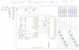
This was the biggest jump in the architecture and was essentially me giving in and realising I needed to go down the hardware PwM route. After a couple of misguided attempts at using shift registers, I found the right component for the job, a Texas Instruments TLC 5940 hardware PwM unit. It provided 16 native PwM channels with a 12bit duty cycle and 4095 shades of grey on each channel. This unit is serial controlled by the ATMega and offloads the control of the LEDs to a second micro-controller dedicated to the task, so gave me the 10 hardware PwM channels I needed. Combined with the instant on concepts from V4 it allowed me to have a sub 10ms start-up to the circuit and a smooth handover to the effects unit, where I could refine and polish the desired effects given the more granular control over fades (Atmega has only 256 shades vs the TLC with 4095 shades).
V5.1 & V5.2
These final tweaks to the architecture reflect some power protection circuitry concepts that allowed me to better protect the circuits in an automotive environment. Specifically, a transient voltage protection circuit that gave me a hard limited +12 circuit upstream of my voltage regulation circuit that made things much smoother and safer.
One thing common to all of the versions was the need to temporarily bypass the effects in case a particularly anal MOT tester decided he wasn’t going to pass it with this unit installed. As a result the need for an MOT switch has always been present, however the way it is handled has changed over time. As of V4, the use of the mosfets allowed for a rather cool and quite awesome way of dealing with this issue. Essentially, what happens as explained before is that the +12 & +5 circuits power up and hold the mosfets closed allowing the LEDs to run on what is a standard power circuit with no PwM. The ATMega has a digital output connected to the +5 circuit that connects the Mosfets and once its booted it sets this output to a “LOW” state which essentially drags the circuit to ground and opens the mosfets so the PwM control can happen. All the MOT switch now does is literally break that connection, leaving the Mosfest closed and the LEDs lit without any interaction from the micro-controllers.
A very neat side effect of this is that this has created a “fail on” redundancy to the brake light. What I mean by this is that if the ATMega or TLC fail the LEDs will still light as normal, they just wont do any effects. This is a great safety feature as the components most likely to fail are these and if they do, the brake light still works like any other brake light would.
What does it look like?
The final schematic is below and available for download here (You will need a copy of RS Components Design Spark if you want to edit it, else there is a PDF in there for normal viewing & printing. Design Spark is free btw, and very awesome!)
What about the code?
The code is very simple. It simply provides the three primary states of operation for the desired time periods required. The three states of operation are:
- Full On
- Breathe Effect
- Larson Effect
Each state of operation is timed for a specific period to allow for typical use, for example, the initial state of Full On, i.e all 10 LEDs on at 100% power, is set to exist for 2 seconds to allow for short presses of the brake pedal. The next sate is the Breathe effect, where the luminosity of the LEDs is reduced from 100% to around 25% over a 2 second period, and then restored back to 100% over a further 2 seconds. This provides a very smooth breathing style effect that runs 3 times or about 12 seconds, which is ideal for longer “slowing down” style braking, before handing over to the final effect. At this point the Larson effect takes over and literally runs back and forth in a loop indefinitely from this point forward, as if you have had your foot on your brake pedal for more that 12-14 seconds chances are you are coming to a stop from high speed, or your sat in traffic stationary so such an effect is either going to help attract attention to your deceleration, or make someone behind you smile for a second as they remember Kit from night rider!
Given the unit only powers up when the brake is pressed, I didn’t need to handle interrupts, or additional switches to make the effects happen, as they run from boot each time, so a simple millis() counter is sufficient to work with as it always starts from zero.
The final code is a typically hacked/adapted version of a million tutorials and is split into a few sections. Each main “void” handles the primary effect functions, i.e Breathe & Larson, then the final void loop just knits them together in the desired quantities. All the horribly complex stuff required to run the TLC is handled by a library that you need to install into your arduino projects libraries folder to make it all happy, which is fortunate as its a proper nightmare without this!
The final code is available here to download ready to go into your Arduino IDE, don’t forget you also need the additional library for the TLC which you can find here.
So how did the prototype work out?
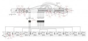
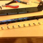
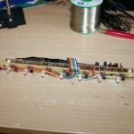
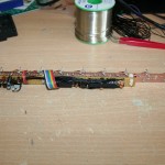
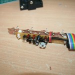
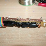
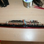
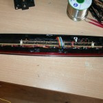
The problem with the prototype was that I wanted a like for like replacement part for the current bulb bar which limited the available space to work in. Essentially I had a space 300mm x 16mm x 30mm which meant it had to be very long and thin. The second major issue with this was that the LED’s would have to be spaced about every 30mm so that meant that I couldn’t just make one long circuit board, I had to have two, one for the LEDs and one for the logic and power. That lead me to the prototype design which took a while! Essentially what I have is two separate boards, one for the LEDs and one for the Logic and Power. They are bolted together using nylon bolts & spacers and then a ribbon cable provides power and PwM control between the two. the final design fits within my space constraints (just) and clips onto the back of the reflector housing perfectly, with just a power and earth back to the original connector for the high level brake light.
Below is a screenshot of the breadboard layouts from Visio:
These are accurate and can be used to build your own, so feel free to use them. Here is the original Visio version which may be more helpful to you.
Once its all bolted together it looks a little bit like this:
What does it look like in the car?
Well I like it, but then I am a bit geeky like that and like a flashing light or two, so decide for yourself !
Here is a nightime video for much better effect… The Cylon starts at 3:00 mins in:
Where next?
A few mad people are interested in having this in their own Alfas, so I have committed to designing a final PCB layout that can be manufactured, if enough people commit to buying one. Other than that, I plan on a few more Arduino based projects in my car, so more will definitely follow!


