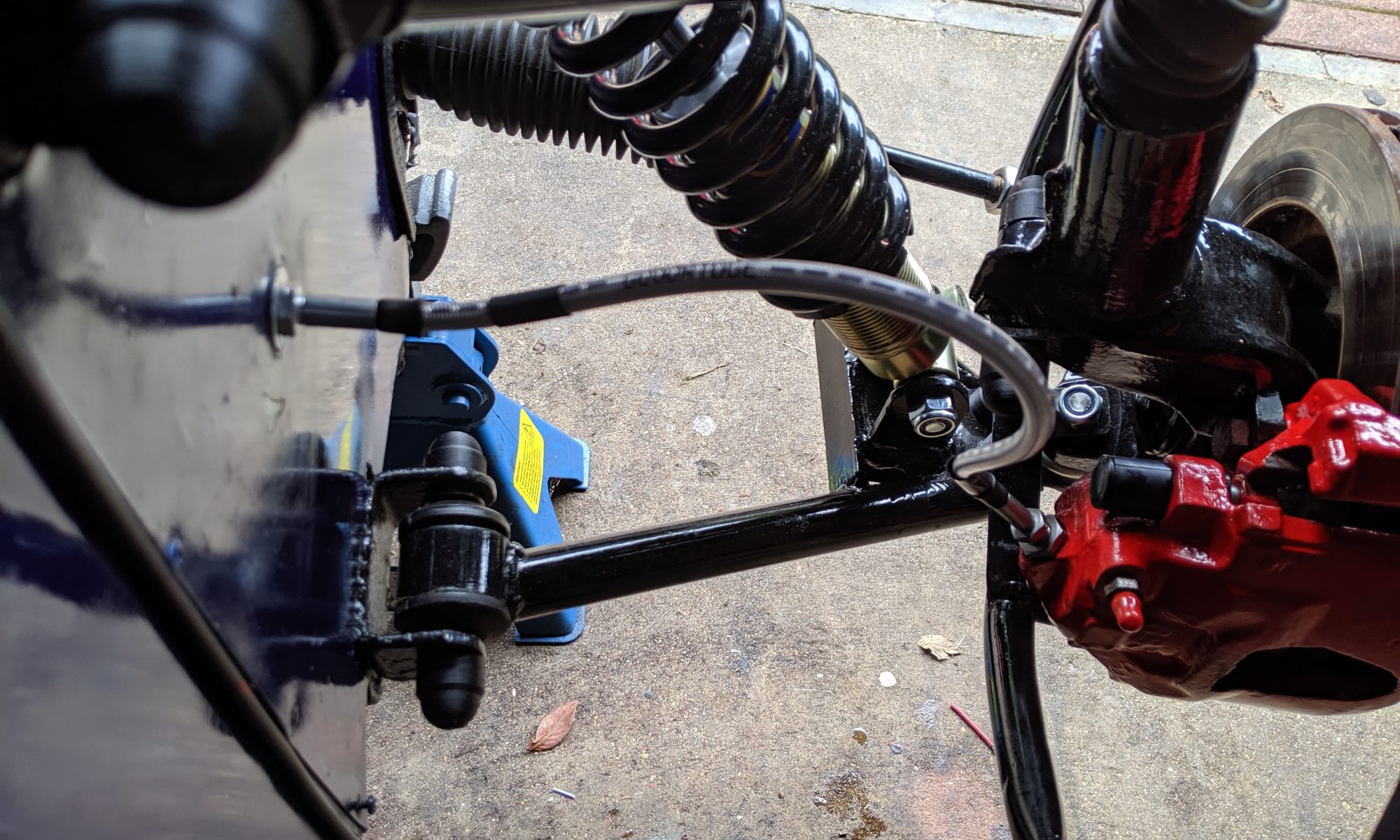
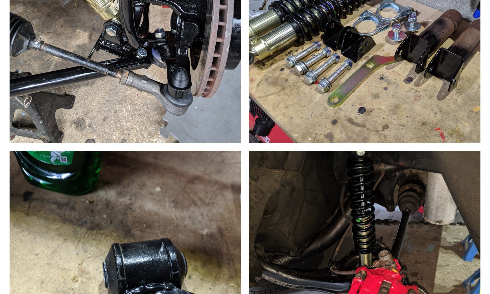
Welcome

Welcome to my digital home! There are lots of articles you might find helpful buried in this site on topics such as modifying an Alfa Romeo 159, rebuilding a Lotus 7 (Robin Hood 2B), not to mention a ton of stuff on technology in general. It’s all here somewhere, so use the search function or navigate using the menu structure. if you want to talk, reach out via the contact function, I usually do answer!

Random Post Selection
GeneralI decided to write this how-to as there are no specific guides on Ubuntu 8.04 LTS for the net-4501, and it took a combination of configs from two completely  different approaches from two separate guides to get it all working. I have found that the easiest way to build for the target platform of the Soekris is to make use of the QEMU emulator, freely available in Ubuntu. It lets you perform a typical installation, the way you would do for any other platform so its less confusing. That said, there are a couple of slight differences and gotchas that this how-to will cover. Step 1 – Preparation Aside from a Soekris device you will need a CF card, whatever size you require, I tend to use 8GB or higher as they are quite cheap nowadays and a card reader in your host platform. To perform the installation you will need a host platform running Ubuntu. What ever you have lying around, or a VM will do the trick. Install QEMU on your host platform if its not already installed: sudo apt-get install qemu make a build folder and download the Ubuntu 8.04 LTS x86 Server Release into it from here: mkdir build cd build wget http://releases.ubuntu.com/8.04/ubuntu-8.04.4-server-i386.iso . Once your environment is ready its time to prepare the CF card. As we are going to use QEMU to emulate the platform and allow a typical installation, we dont need to manually create the partitions on the card. All we need to do is ensure that it is 100% empty. Install your CF Card and if it mounts as a partition, unmount it from the command line: umount /dev/sdc  NB: you can determine the device it is detected as by running the dmesg command and noting the device it is assigned. It will likely be sdc or sdd as the card will be seen and used as a SCSI disk device.Now you need to ensure that it has no partitions on it. run fdisk and delete any partitions listed: fdisk /dev/sdc The commands you will need in fdisk are:p = Print partition tabled = delete partition (you will be prompted for a number)w = write changes to disk? = help Step 2 – Installation Now you have a blank CF card your ready to run QEMU and start the install. This is actually very simple as QEMU can be controlled from the command line, so all you actually need to do is type the following command: qemu-system-i386 -m 512 -hda '/dev/sdc' -cdrom 'ubuntu-8.04.4-server-i386.iso' -net nic,vlan=0 -net user,vlan=0 -localtime -no-acpi This will launch a window and present you with the Ubuntu installation program your already familia with. The only notable option within the installation is when prompted to configure your disk layout, use “Guided” without LVM and use the full disk available. if you use LVM it will add an unnecessary overhead and as the net-4501 is a GEODE Processor with 133mhz clock and 64Mb ram, overheads are not ideal.Once it has completed its installation, reboot and allow the newly installed OS to boot up in QEMU once more. Step 3 – Configuration The one drawback I have found with QEMU is that you cannot copy and paste between the host and guests. This is a bit of a bind, but fortunately there are not a lot of configuration changes to make. The first major change we have to make is to swap the kernel for one that does not require PAE extensions. To do this, type the following: sudo apt-get install linux-image-generic Now we can configure the serial port listener using your favourite editor (vi, nano etc.. I prefer vi so will use that in the commands): vi /etc/event.d/ttyS0 start on runlevel 2 start on runlevel 3 start on runlevel 4 start on runlevel 5 stop on runlevel 0 stop on runlevel 1 stop on runlevel 6 respawn exec /sbin/getty ttyS0 115200 Next we need to configure grub to use a serial port: vi /boot/grub/menu.1st Somewhere near the top of the file add the following two new lines: serial --unit=0 --speed=115200 --word=8 --parity=no --stop=1 terminal --timeout=5 serial Now, find the line that looks like this: # defoptions=quiet splash and change it to look like thgis (keeping the hash): # defoptions=splash console=ttyS0,115200 Finally we need to load some modules early on or it wont be able to use the CF as a disk to boot from: vi /etc/initramfs-tools/modules Append these lines to the bottom of the file: ext3 ide_generic usb-storage The last thing to do is to force an update of the changes we just made so run the following commands: Update-inintramfs -u update-grub For good measure you can always run: apt-get update && apt-get upgrade but it is optional ๐Ÿ™‚ Now all that is needed is to power off the QEMU instance: poweroff and remove the CF card from your host. Step 4 – Finishing up The final thing to do is to sync the baud rate of the Soekris device to the baud rate we have used in the configs. By default the Soekris is set to 19200 baud, but we have used 115200 baud in teh configs to make things a little better to work with. We need to sync these for ease of access later on, so first open up your preferred terminal application and connect to the Soekris at 19200, with no CF card installed. At the boot prompt type: set conspeed 115200 Once this is set, you can power down the Soekris, install the CF card in it and boot it back up. It should boot to a prompt quite happily and your ready to configure your new embedded Ubuntu device however you need ๐Ÿ™‚ Enjoy! ——————————- FAQ Section: Q: Why are you using 8.04LTS and not a more recent release? A: As of 10.04, Ubuntu dropped support for all 486 and older style CPU’s on the premise that most people would have modern computer systems. This is a deviation from the ethos of Linux in my opinion, but it was their choice to make! I have spent weeks trying to build later versions of Ubuntu on the 4501 platform, and have built custom kernels with the right modules etc, but have NEVER had success. Your welcome to try though ๐Ÿ™‚Related Images: [...]
Alfa 159 / ElectronicsFor a while now I have been looking into alternative power solutions for the Alfa due to its power hungry nature that is not helped by the many auxiliary systems I have added over time. For the most part, the stock battery can cope just fine, but I have always wondered about the use of capacitors and what real value they hold. In years gone by, the capacitors you could get hold of were simply not that useful. A 1 Farad 12v capacitor like you would use in an car audio installation was simply too expensive and had far too little power storage.  One reason I had been considering capacitors was not for power storage but for the side effect of cleaning up the overall noise introduced by the power system in the car. This would serve to improve the overall sound quality of the entire system as well as benefit all electrical systems with a cleaner supply. A good explanation and test is here: https://youtu.be/T9mlvbF0flM Capacitors have come on a long way though and the new generation of “Super” or “Ultra” Capacitors are starting to become a viable alternative to a battery in a car. Because of this, I thought it only sensible to buy some parts and see what it was all about ๐Ÿ™‚ Here is a video of a car replacement battery using 6x 2.7v, 500F super capacitors to show you what I mean: Obviously starting the car and providing long term, offline power for the systems when its not running are two different things, so if you seriously wanted to replace your traditional battery you would need a hybrid solution that combined batteries with capacitors.  I’ll be looking into that next ๐Ÿ˜‰ Super capacitors come in a few common shapes and sizes but by far the cheapest for the power are the common 2.7v 500 farad units. To hit the target voltage I needed (12-14v) I needed a few wired in series to increase the overall voltage. Fortunately this is a common solution as its a typical voltage used in solar installations. Wiring the capacitors in serial actually decreases the overall farads of the bank, so 6 x 2.7v = 16.2v but the farads are divided by 6 to give you 83.333F. You could add a number of additional banks in parallel to bring the farads back up, but it starts to get a bit big then and you would be better looking into a different style capacitor. such as the Maxwell Ultra 2.7V 3000F, 6 of which would deliver a 16.2v 500F pack ! Also, a point of note is that even though the planned bank has a capacity of 16.2v it will only operate at the voltage its charged too, so if the car charges at 13.5v then the bank will be charged to 13.5v. Its also important to balance the load across a serialized bank of capacitors to prevent damage. Fortunately due to the commonality of the target bank design, a balance board was readily available: The plan was to build a 12v 83 farad bank that would act as a power reserve for the bass amplifier in the boot as this would be a good starting point and bolster the overall power system on easily accessible, existing 4AWG wiring I first bought a few common, cheap and easily accessible parts off ebay: 6 x Green-Cap (Black) Super Farad Capacitor Parallel Battery 2.7V 500F 35*60MM @ 26.99 6 String 2.7V Super Capacitor Protection Balancing Board 100F – 500F 240x40mm @ 8.75 10 rubber lined 35mm pipe clamps @ ยฃ7.29 8 AWG power cable with in line fuse holder and fuse @ 4.99 So for less than ยฃ50 I had everything I needed for the experiment. I could have bought a pre-made board with unknown capacitors on for about ยฃ26 but I have read a few things about the capacitors being junk so went for a known good brand and DIY. I first assembled the capacitor bank with the balance board to achieve the target solution. Hot gluing the capacitors to the board before soldering them to make sure the finished unit was as solid as possible. It took some real heat on the iron to get the solder flowing, especially soldering in the 8AWG wires. I soldered the 8AWG cables directly to the board to ensure maximum power transfer: Once the bank was ready I used the pipe clamps to install the unit in a free space within the amp enclosure and connected it to the positive and negative 4AWG distribution blocks I already had in place from the original installation of the enclosure: I must admit, I was extremely worried when I first connected the fuse that it would just explode in my face, so it was a tentative and careful moment! Some people recommend installing a resistor inline initially to slow charge the capacitors and protect the systems in between, but as I was on a 4AWG connection direct to the battery I was not worried about the charge / discharge issues. They did make a fizzing sound for a few seconds when they took there initial charge but I was stood by with a fire extinguisher!  Once the fizzing stopped and nothing looked like it wasd going to explode I checked the units for discharge / earth shorts and also for temperature. As everything was ok, I decided to start the car and run the amp. The car started quicker than normal so clearly the extra high current supply had already made an impact on the overall electrical system. Its actually possible to start and run an normal engine on a bank of capacitors like this and replace the battery with them as can be seen in one of the videos at the top of the page. Although for the Alfa, I would need a larger bank with more capacity as the 2.4 is a bit of a power hungry beast! I ran a Bass test loop to get the amp hot and push the sub to its limits for 30 minutes. The amp got very hot as expected but the capacitors only got a little warm which is great as if they got very hot that would be a problem. Once it was all back together you could hardly notice the upgrade unless you looked very closely at the vent holes! All in all this was a great upgrade and I am definitely going to explore more super capacitors in the engine bay in some sort of hybrid battery/capacitor solution next! Related Images: [...]
GeneralIts a strange thing when you suddenly realise the simple truth about something. The fact of the matter is, I am bored with mixing! What I mean is, simply firing up the 1210’s and spinning a few tracks just doesnt do it for me anymore. I think this is a trend that is also reflected in the current dance music scene. Consider a true talent in the scene today, such as Deadmou5, vs an old skool DJ like Dougal or Vibes? The once,  “studio only” production techniques are being utilised on the fly to bring dynamic, real time remixes to the clubs. This is something that really interests me, something I want to pursue further. MP3’s are part of the equation, but so are real-time sequencers like Ableton Live, sample pads, real-time effects processors and a lot of time spent creating, dissecting and amassing lots of custom loops. Put all this together, and you have what the scene now desires, and what I personally want to give. Watch this space…. Related Images: [...]
Alfa 159 / ElectronicsWell, I continue to work on this and now have a beta unit in my car on a long term test. It is pretty rough around the edges and has one major(ish) issue that I am working to resolve, but its a good starting point to work from. So what I have now looks a bit like this: (click to enlarge) Its still a very simple design that uses as few components as I can, but as a result it has some issues: As the the LEDs are quite hungry (50Ma each) the ATMega328 & the voltage regulator has to work hard to feed them. The above point causes a small delay in start-up of the unit of around 200-300ms. This delay is a problem as the unit is powered by the feed to the brake light, when the brake is pressed, so in essence it adds a small delay between the stop/tail lights of the car illuminating and the high level brake light. Long term this is unacceptable, but for now its a work in progress so I can live with it. The first generation PCB was designed to fit into the dust cover of the brake light, but after I attached the ribbon cables for the LED’s it didn’t fit so is now wedged under the parcel shelf for now. This gives me easy access form the boot to change the unit as I progress the design to remove the delay and make it instant. Here is the mock-up of the PCB using matrix board (left to right we have the finished design, the component layer, the jumper cable layer on the front, and the soldered join layer on the back):        And the finished article looked like this: In the end I decided to opt to hot glue the LED’s into the reflector and wire them back via a ribbon cable to allow me more flexibility on changing the circuits easily: Long term I intend to make a unit that can replace the original light bar, so the LEDs will be mounted direct to a PCB that will be installed into the light bar in some way, or easily attached to the back of the reflector housing, not sure which yet. I am working on a number of new designs at the minute that remove the delay and am getting some help from a true expert in the field of automotive electronics who actually designed stuff  that is used in the Mclaren MP4-12C. The current V3 unit that is in the car looks like this when operated: You can download all of the project files (sketch, layout & schematic) from the downloads section. Watch this space for V4 of the unit. Related Images: [...]
LiveMixeshttps://jabawoki.com/wp-content/mp3/Jabs_20092001_Summer_House.mp3 Podcast: Play in new window | Download Related Images: [...]
RH2B Build DiaryAnother big issue with the hoody was the tune. It was all over the shop. really rough and just a bit shit. This was an easy fix though, I just needed to add a 14point7 Spartan 2 Lambda to the Megasquirt ECU and get some help! Lambda ready to go in! The main issue with the current engine setup is the horrific ITB’s (f you can actually call them that). They are difficult to balance and will eventually be replaced with a whole new setup I am building on a new engine. That said, they needed to work for this summer so I called up a guy called Shaun who runs MS2 Tuning and knew the car from its previous owner. Shaun is awesome. A really friendly guy that gave me, a total stranger, support and advice over the phone and then came over to help me to a basic setup tune on the car for beer money. You dont get much better than that in this game. After about 3 hours playing, diagnosing and fixing some earthing issues, we had the ITB’s balanced, the AFR dialled in, and the engine was purring. This was exactly what I had hoped for and the potential I knew was in the car when I bought it. I do love an underdog! Related Images: [...]
InfoSecSo here we are again, a few months on, and just when so many were licking their wounds after the last infection, along comes another. Guess what, if you had your eyes shut my sympathy is not going to be that forthcoming! Malware has come along way since its anarchistic pre-pubescent ย ย beginnings, and is now a fully fledged teenager, displaying all the fire, passion and unpredictability you would expect from one. Once upon a time, you could be sure your malware was simple in its intention, written by an unorganised person or persons, with the typical agenda of notoriety or malicious damage. Although bad, quite easy to deal with. Modern malware however is a whole new ball game. Written to order, with a menu of “features” available from stealing data to placing a sleeper inside the system, all with standard issue mass infection mechanisms anti malware detection programming, the latest in self defence techniques and with the underlying drive of a typically well organised or at least very motivated source. Yet despite this significant step change in what we are seeing as the attack, as a world of experts I am still not seeing a change in the controls, strategies or defence tactics of many organisations. This I find astounding. How anyone who is considered a responsible person in an organisation can sleep at night thinking that a firewall and a few layers of Anti-Virus is going to cut it as the total form of protection is seriously miss-informed. Equally, those companies out there pedalling the silver bullets of the security world ” ultimate anti-malware solution (TM)” are doing nothing but compound a problem that will continue to evolve and get more sophisticated. The simple fact is that ANY malware solution on the planet today from any vendor works on the same detection methods. They look for something they have seen before or something that looks like something they have seen before and block it, It’s that simple. And for that reason alone, you cannot rely on that control alone as the only form of defence. Equally, the firewall and all that other perimeter based paraphernalia you invested in, don’t get me wrong, all well and good, but its not going to stop this stuff. Why? Web 2.0, Social Networking, Unified Communications, Chat, Mail, you name it. Any medium of communication that can facilitate the transfer of a file, and that includes just good old browsing of the web, will bring malware to your door, invited in so to speak, through all that perimeter protection, and straight to the desktop. The truth is, the only way to protect yourself against this stuff is to stop thinking it’s “the good old days” and get with the times. The only way you’re going to stand a chance of surviving one of these incidents is by thinking about the entire control landscape and how they interact with each other. A good model for this is Defence in Depth as that provides a very good method of visualising the controls at each layer of your environment and allows you to map attacks through the controls to see if they would be successful or not. This simple visualisation strategy can bring value beyond your wildest dreams, giving you the opportunity to stop, think and adjust what you’re doing, justify investment, demonstrate control and rationalise spend. All very important concepts for the times. There is a world of products, vendors control choices and equipment with pretty flashing LED’s on it. The only way to figure out which ones will help you is to understand what you have, what you need and why. Related Images: [...]
General…..put simply, because you have to! Now, don’t get me wrong, there are a thousand reasons for the upgrade, but did you know about this one? There is actually a very serious and technical reason that you should upgrade. I’ll try and explain it to you in lay terms…. The current “2G” iphones operate on the GPRS/EDGE Networks (I won’t get into the technical stuff, use wikipedia for that). Now you will think that actually that’s a good thing, better data usage is good news surely? Well it would be if their was not one simple problem with the 2G network. That is that you cannot use voice and data to the same endpoint (i.e. iphone) at the same time!!! Yes, that’s right. You cannot surf and chat simultaneously! Now, this has never really been a problem before a device like the iphone, as most of use would use the data facilities on our nokia or sony so infrequently that we never noticed a problem, however the iphone, being a data hungry beast, is a regular user of data, without your permission! What this all equates to is simple. If you iphone decides it needs a data connection, say to update its email or something else useful, and at the same time, someone tries to call you, guess what, they don’t get through! This kind of defeats the object of the iphone qualifying for the use of the word “phone” IMO! So whats the answer? simple, upgrade to a 3G phone! this makes use of the new third generation network (HSPA/UTMS), which of course, being data centric, allows simultaneous use of voice and data from a single device. What more of an excuse do you need to go and get that upgrade? Related Images: [...]
RH2B Build DiaryThe bonnet on the hoody is metal, in two sections, and was bolted together on a centre flange. This left a seam that was filled with filler and then a vinyl stripe laid over the top. Now this would have been fine except for the fact that the builder then installed a long pneumatic ram (the type that opens a boot on a hatchback) to hold up the bonnet when you lift it. Great for convenience but done in such a way as to cause a long term issue. Essentially, as the weight of the bonnet and nose cone were pivoting on an M8 bolt attached to the centre flange (2 x 1mm steel), the flange had twisted, bent and caused the bonnet to deform above. This in turn caused the filler to crack and separate from the bonnet, which then caused the vinyl to crack leaving an unsightly jagged line down the centre of the bonnet. Bonnet damage after removing the vinyl and cracked filler. Rather than just filling it and applying another vinyl sticker to it, knowing it would just do the same again, I set about designing and printing a better solution to the mounting of the jack point to the bonnet and also reinforcing the flange with several additional M8 bolts! A few iterations in Fusion 360 and 3 test prints in PLA, I had a final design that met the profile of the bonnet, bolted through the flange, spread the load of the bonnet more evenly and provided a solid anchor point for the jack. Design iterations The final design is pretty cool. It spreads the load exactly as I wanted and prevents the centre of the bonnet where the filler is being pushed up. It has also added rigidity to the panel as a side effect. Finished mount Once the mount was installed all that was left to do was fill the resulting gap with a flexible filler that wont crack and fall out, sand it smooth(sh) and the re-apply the vinyl. What I learned from this experience is something I was already pretty cognizant of. I cannot do bodywork!!! I dont have the patience for it at all! Finished article. Its by no means perfect but will do for now! Related Images: [...]
InfoSecThis is a short video explanation of how the UK Cyber Security Challenge’s launch cipher was put together, and subsequently how to break it! C4Odla8I0Hs Related Images: [...]

Related Images:

Related Images: