

Welcome to my digital home! There are lots of articles you might find helpful buried in this site on topics such as modifying an Alfa Romeo 159, rebuilding a Lotus 7 (Robin Hood 2B), not to mention a ton of stuff on technology in general. It’s all here somewhere, so use the search function or navigate using the menu structure. if you want to talk, reach out via the contact function, I usually do answer!
Random Post Selection

GeneralWell it has been a while since I treated myself so the other day I stopped by West End DJ on my way into the office and I picked up an Akai APC 40. In fairness it was my birthday and I used that as a feable form of excuse for the expenditure, but I have a semi clear conciense as a reslut and another oh so sexy toy to play with!
This toy really is the ultimate in Ableton Live control, extending the interface litterally to your fingertips and bringing a whole new world of possibility. You can read all about it on Akai’s site, but if you really want to see the potential, check out these YouTube links that just sum up the potential in full from my perspective:
Ok, so its going to take me a while before I get this good, but thats what its all about.
……watch this space 🙂Related Images: [...]
GeneralI have decided to plan my new musical platform in advance this time, rather than the usual method of buy something, expand on it, realise its not up to the job and then replace it. This essentially means that I am going to spend a great deal of time on google deciding something, then finding a better version of something and so one, until I eventually bite the bullet and invest.
What I have at this stage is a premise and an outline set of requirements. The premise is simple, go fully digital, but retain analogue controls. The outline components are as follows:
A powerful PC/MAC + Essential Apps such as Ableton Live
A High Quality Multi-channel sound card
A midi trigger device
A Good quality Mixer
A Sampler/Effects Unit
Now, its actually possible to have all of the above in a single box, and in fact, many solutions exist for sub £250, but to be honest, its just not going to give me the flexibility and expandability that I desire. What I want is complete fluidity in the solution so that I can expand upon for many years, giving me not only multi-channel mixing, but the real-time remix capability that I desire
So where next?
Well, I already have a decent mixer (DJM600), a powerful PC (Multi-Xeon Monster) and Ableton, so the most important piece and crux of the system is what I need to acquire first. This would be the multi-channel sound card! I have had a look around and found many options, but this one seems to be the best by a mile:
Motu Ultralite MK3
This unit has all the features I could need, from 192Khz sample rates, through to 6 channels of input and 10 channels of output to give me as many feeds as I could possibly deal with! The spec list goes on forever on this thing, which is why it can command a £500+ price tag. But if I am going to invest, this is the way forward.
Related Images: [...]
Alfa 159I finally got round to installing the Wireless OBD II dongle I bought off ebay into my car the other day and thought I would document the process for those that may be interested.
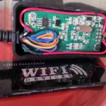
First your going to need to pick one up. I bought a clone Kiwi Wifi dongle off ebay for £45 which is a third of the cost of an original branded version so a complete bargain! Its a great little unit and perfect for interfacing with any OBD application you may want it for. Once you get the unit delivered you will notice that it is a simple plug and play job with no configuration. While this is true in its simplest form, one slight issue I found is that the OBD port is always powered up, therefore you would have to plug it in and remove it when you were not using it or it would always be broadcasting direct access to your cars ECU via a wireless network, which in my book is not the best of ideas!
So the first job you have is to retro-fit an on off switch to allow for a more permanent installation! Its an easy job and Maplin have micro 12v switches that will fit and do the job well for a few pence. Just slide your fingernails around the edge of the front plastic cover and it will literally pop off in your hands, giving you access to the internals. All you need to do is de-solder the power connection (trace pin 16 on the connector), add a new bit of wire from the board to your switch and back to the original wire where you can splice it back together. To do this nicely you need about 12cm of wire, 2cm of heat shrink wrap, a soldering iron & solder & a small switch.
Fit the switch on the side of the unit for easy access and put the cover back on with a dab of glue to hold it in place.
Here is an image of my modified unit.
Once the unit is installed in the car, you can connect it to your chosen application which for me was Rev2 from Dev Toaster on the iphone. This app is a bit pricey at £26 for the pro version, but gives me everything I want in terms of access to key metrics in real time, full data logging and even engine code interrogation and resetting! It can get data on a large number of points including:
Vehicle Speed
RPM
Fuel Consumption
Engine Coolant Temp
Fuel Pressure
Calculated Engine Load
Throttle Position
Intake Manifold Pressure
Air Intake Temp
Timing Advance
Mass Air Flow
Fuel Level
Barometric Pressure
EVAP System Vapor Pressure
Fuel Trim
Boost
Examples:
In terms of the actual connection between the iphone and the OBD II dongle, its as simple as:
Connect the OBD II and power on
Go to settings > WiFi on the iPhone
Press the arrow next to “CLKDevices” network
Set a static IP of192.168.0.11 & netmask of 255.255.255.0, save and exit
Open Rev2, go to settings, hardware choose Kiwi Wifi, then select custom from the bottom
Set the device to 192.168.0.10 and port of 35000
Done.
From this point your up and running!
You do need to configure a profile for your car, with its kerb weight as this is used to calculate torque and BHP. My kerb weight is documented at 1680KG, but I have the top spec TI version with all the extra trimmings so expect it to be closer to 1750KG. I am of course excluding the 75KGs of lard I personally add to the equation, but I think thats fair! I will actually get it weighed at some point just to be pedantic, but for now 1750kg’s is close enough for me.
http://www.youtube.com/watch?v=NWvbQ1RdHCo
Related Images: [...]
GeneralThe Problem:
Ok, so anyone who has worked with sound equipment before would have been greatly disappointed shortly after taking the M-Audio Xponent out of the box. Essentially, it’s a bit crap. The main bug-bears are the faders, often referred to as being made by “Fisher Price”.They are loose, and generally feel nothing like a proper mixer, so anyone used to using pro audio equipment is going to feel short changed (I know I did!). That said, once you get over them, and there are some tricks you can apply to make them feel less annoying, the other primary bug-bear is Torq. This software can only be described as an epic fail! I gave it a shot, I persevered with it for a long time, and have come to the conclusion that its beat detection engine was programmed using chaos theory.
I have mixed on many different platforms, decks (belt and DD), CDJ’s (from first gen to modern) and midi software from TraktorScratch V1.0 through to the usual suspects of today. What all of these platforms allow you to do is beat match with little effort if you’ve got a good ear. Torq on the other hand, seems to want to fight this process and in my own experience, creates a clinical/harsh environment to align beats without getting nasty overlay (beat on beat cancelation). If you persevere I am sure you can personally compensate for this and actually become good at “mixing with Torq” but IMO I don’t think it appropriate to change my mixing style after 20 years just to accommodate crap software.
This problem brings us to the solution I have discovered. I don’t take credit for pulling this together, many people better than me have toiled long and hard to make this work and have done some excellent work on the subject. All I wanted to do was have a rant, show you how easy it is to make the Xponent better and then credit those who did the work.
The Solution:
Native Instruments have invested a lot of time and energy into refining the Traktor product to what it is today. I have used different iterations of it since Scratch v1.0 (the first ever version) and it just keeps improving! The most recent version is Traktor Pro V1.x, I am using 1.2.4 and it is truly phenomenal. I won’t go into it in too much detail, but will say this much, its intuitive, just like it should be, has some amazing effects available out of the box and “just works perfectly” What more could you ask for?
Of course, Despite the Xponent being a Midi Control Surface and a Sound Card, it’s been locked into Torq to proliferate the spread of the evil program, but, there is a way you can break out of this and turn your midi control surface back into a programmable 2-way midi surface like any other. It’s actually quite simple:
While you switch the device on, press and hold the number 2 Queue button + the Lock Button on the left deck. It’s that simple, hold them till it’s all booted up, and to check its worked, press any button, if it lights up then fades away, it’s not worked and you need to power off and try again. If it does not light up, you’re in business and you have a midi control surface ready to use with any Digital DJ software you want!
At this stage you have a couple of options, start mapping the buttons yourself or grab a map that has already been put together. Personally, I like to short-cut things, so I would grab a predesigned map. After a good look around and a few failed starts, I found a mapping from HolyCT based on the work of DJ Kad listed in the NI Forums. It is amazing! It has all the mappings you would want, full documentation and even a browser mode so you can use the jog wheels to browse your track lists without the keyboard and mouse! It makes use of the X/Y Pad and is IMO a very well put together map for the Xponent.
Bringing the good features from the Xponent to a well written and user friendly piece of software like Traktor Pro, is a marriage made in heaven! I am truly blown away with the usability and playability of the combination, and it has convinced me to stick with my Xponent for the time being. It may not be the best controller in its class, but it has some cool features and once you get used to the faders, it’s not all bad!
Related Images: [...]

LiveMixeshttps://jabawoki.com/wp-content/mp3/Jabs_20092001_Summer_House.mp3
Podcast: Play in new window | Download
Related Images: [...]
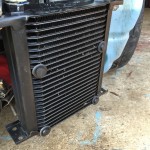
Alfa 159After the successful modification made to the gearbox cooling system https://jabawoki.com/2016/01/27/alfa-159-gearbox-cooler-modification/ I found that, while the cooling was perfect while the car was moving over 30mph, there was an issue at lower speed.
On more than one occasion I found that if I sat in traffic, slowly edging forwards towards a busy roundabout, once I got to the roundabout and accelerated away, I would have a shift flair for the first gear change. This would disappear by the second change so was clearly a cooling issue where the lack of airflow meant that the gearbox temps would rise in traffic until you had airflow again.
The fix is/was simple. I just needed a thermostatically controlled fan adding to the radiator so that I could generate airflow at low speeds.
After doing some basic research I found a really nice 5″ fan from SPAL, available from Merlin Motorsport.
This unit was very high power and perfect for the job but I needed a thermostatic control solution as well. Merlin had the ideal solution as well, a Davis Craig Thermostatic Adjustable Fan Controller.
This fan controller was ideal as it had a separate external temp sensor that was fitted into the radiator itself which meant I did not have to cut into the oil lines to make the mod.
Fitting required removal of the bumper as usual, but that gave me an opportunity to fix a crack that was temporarily repaired previously.
Adding the fan was very easy as it came with its own mount kit that essentially used special plastic ties that passed through the fins of the radiator and clamped it securely to the rear of the unit.
Fitting the fan controller was a little more tricky but only due to the very short wire run on the temperature sender which meant it had to be within two feet of the fan. Fortunately it nestled perfectly between the ECU and the headlight!
The unit can control two fans but I am only using it in single mode. It has an adjustable temp trigger so mine is set to 75C which is a reasonable point to start testing from. The added digital temperature display is also quite useful for diagnostics!
I will have to see how it pans out but I am pretty confident that this will sort the last pesky shift flairs for good!
Related Images: [...]

InfoSecI recently was asked by Bloomberg to comment on the raft of Android malware recently discovered. During that interview I mentioned some concepts around the open vs closed models and wanted to expand on this thinking a little further.
As you may know the Google Android platform has been open source since 2008, and as such has a healthy following of developers and an open list of problems that anyone can view and contribute fixes for. Contrary to this, Apple IOS has, and most likely always will be closed and the intellectual property of Apple, and therefore is managed by an army of developers working directly for Apple. Other than these two business models being the polar opposites of each other, the devices themselves do share some common ground, an example of which is they are both based on a *nix base and both allow anyone to develop an application for their platform.
So which is better, open or closed? Both have equal merits and demerits, but for me the key one we need to consider is the security of the applications. Given a smartphone platform is ultimately a portable computer in your hand that you can transition a significant amount of daily communications to, in any corporate environment you need to be thinking about how you maintain the security of that device. For the purposes of this article I am going to discount all the other major security problems with both platforms and specifically look at the apps. To this end I want to create the abstraction between the platforms and the application environments as people seem to confuse these two and blur the lines, and forget that we aren’t talking “open-source” as both platforms are in fact “open-shop”.
If your app store is 100% open, as we have seen with Android, anyone can release any app into it without any form of quality control or security audit. This, as we saw, resulted in a number of applications having more functions that the user subscribed to, and left the devices open to abuse from those individuals that would make money from negative actions. In a corporate environment this means that you have got to control what apps get put on the phone, and create a whitelist and policy enforcement system, which as we all know, we cause the end user to get upset as their freedom of choice is restricted. For the general consumer this means that they, at some stage, will likely end up getting literally robbed blind by their smartphone, because, in an open model, there is no one controlling what gets onto their device for them.
The other end of the spectrum is of course where we are with Apple. Onerous quality assurance, technical and security checks and numerous caveats to adhere to, before your app even gets into the store. But this conversely reduces the risk to business and the consumer equally. In this model, Apple takes control and responsibility for securing the applications on their platform, and minimising the risk to the user. I of course, still would recommend in any corporate environment the use of policy enforcement and approved applications, but you’re at least starting for a better place, and don’t need to do a full source code review of every app your planning to use just to make sure it’s not a Trojan of some kind!
So which model is right?
To be honest, both have their merits and both have their flaws, but I still, personally, favour Apples approach, to err on the side of caution and ensure that the apps they release are 100% up to the task. Let’s face it, developers are known for cutting corners where they can to save a few lines of code, so someone cracking the whip on quality and security can’t be all bad now, can it.
Related Images: [...]
GeneralNative Instuments – Traktor Scratch
This is the final choice and the result of much deliberation and research.
It would seem that for the most part its a two horse race, Serato vs Traktor. I’ll give you the highlights to make it simple. Serato is very very stable, easy to use and generally a rock solid solution to mixing MP3’s. Traktor has less reputation for stability but so many more features and possabilities when it comes to taking your music to the next level. This is best domonstrated bythe release of traktor 3.2 and its ability to mix 4 sources in the same interface! this means you could have 2 x decks + two other input sources all up at once mixing through a 4 channel mixer, when used with the Audio 8 interface. It was this feature that won it for me.
With this I can utilise Ableton Live like it was another deck, and have a 4th source as something like a standalone sequencer, drum machine or other random piece of electronic excellence. Now all I have to do is save my pennies and actually buy one! 🙂
Related Images: [...]
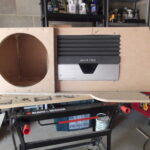
Alfa 159Once the car was pepped and ready it was onto the enclosure build. This was a combination of trial and error mixed with some loose calculations and estimations around box size. I had worked out utilising box design software that for my sub, a 0.6 cuft sealed enclosure was going to give me good responsive SQ and enough power. This also suited my limited boot incursion requirements so was ideal.
I also wanted the amp to be located as part of the enclosure and with the heat-sink visible to aid in cooling. The end result was to have something that looked as close to built by designed as I could achieve without a lot of fibreglass and pain!
” order_by=”sortorder” order_direction=”ASC” returns=”included” maximum_entity_count=”500″]
Related Images: [...]

LiveMixeshttps://jabawoki.com/wp-content/mp3/Jabs_20102001_Progressive_House.mp3
Podcast: Play in new window | Download
Related Images: [...]