

Overview
The Halo units require good, clean regulated power to run or they will burn out. A cars power supply is the exact opposite of this, its dirty, unregulated and a very bad place for electrical items to live! As such, most electronics in a car have additional protective mechanisms to keep then safe. The Halo controllers & rings are no different.
Please refer back to the Parts List to see what components you need for this phase. Also please note that this wiring can be completed at any time, ahead of the Halo’s being installed as it will not effect anything in the car.
Process
The basic idea is to provide a direct feed from the battery to the power supply unit that is switched via the ignition feed, and then to run 2 x power leads from that power supply to the headlight locations ready for connection to the Halo controllers.
Power Supply
Start by opening the bonnet of the vehicle to access the area where you will be working.
- Un-clip the cover to the fuse holder on the top of the battery (Figure 1)
- Remove the lid of the fuse box next to the battery by removing the 3 philips head screws (Figure 1)
Now you will be able to access all the parts you need to.
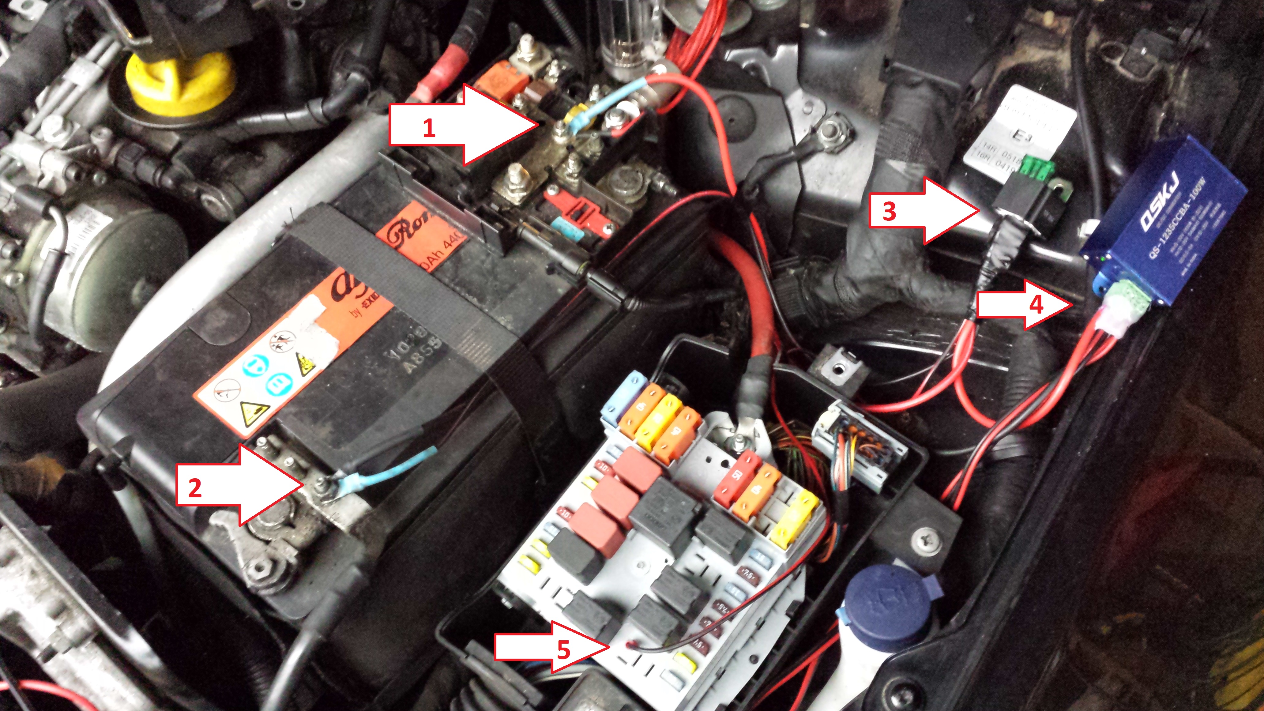
Using Figure 2 as a point of reference, follow the following steps:
- Cut a 18-24″ length of 12v twin core 8.75A wire and crimp circular tabs onto the end of it. It is useful to cut the red / power wire shorter that the black / negative wire so the wire runs neatly along the battery and to leave room to attach the in line blade fuse holder and integrate this unit either through crimping or soldering it in line on the Positive feed. (Figure 2, #1 & #2)
- On the opposite end of that length of wire, crimp 2 female spade connectors and attach the negative one to the connector of the relay labelled 85. (Figure 2, #3)
- On the same length of wire, attach the female spade connector on the Positive wire to the connector of the relay labelled 30. (Figure 2, #3)
- Cut a further 18-24″ Length of 12v twin core 8.75A wire and strip away the positive leaving only the negative feed. Crimp a circular tab onto one end of it and strip 0.25″ of bare wire on the other end. Attach the bare wire end to the screw terminal on the Power Supply labelled “IN -” (Figure 2, #4).
- Cut 6″ of the spare single Positive 18-24″ length from the previous step and crimp a female spade connector to one end and attach it to the relay terminal labelled 87. Strip 0.25″ of bare wire from the opposite end and attach it to the Power Supply terminal labelled “IN +” (Figure 2, #4).
- With the remaining length of Positive wire from the last 2 steps, crimp a male spade terminal to one end and a feral spade terminal to the other. Insert the male spade terminal into the fuse box as show in (Figure 2, #5) and connect the female spade terminal on the other end to the Relay terminal labelled 86.
- Now connect the two negative circular connectors to the negative side of the battery using a 8mm spanner or socket (Figure 2, #2) and the positive circular connector to the positive side of the battery, before the fuses (Figure 2, #1)
You can now test if the power supply is working by switching on the ignition of your car and observing if the power supply’s green LED lights up. If it does not, double check all of the connections as per the above.
NB: I personally found that I could just push the power supply and the relay easily into the space between the fuse box and the suspension turret in my engine bay and the look that runs over the top holds things in place quite well. Your engine bay may be different and as a result you may need to find an alternative location. If that is the case you will need to adjust the cable length suggestions in the above steps to account for a different location to be used.
Figure 1:
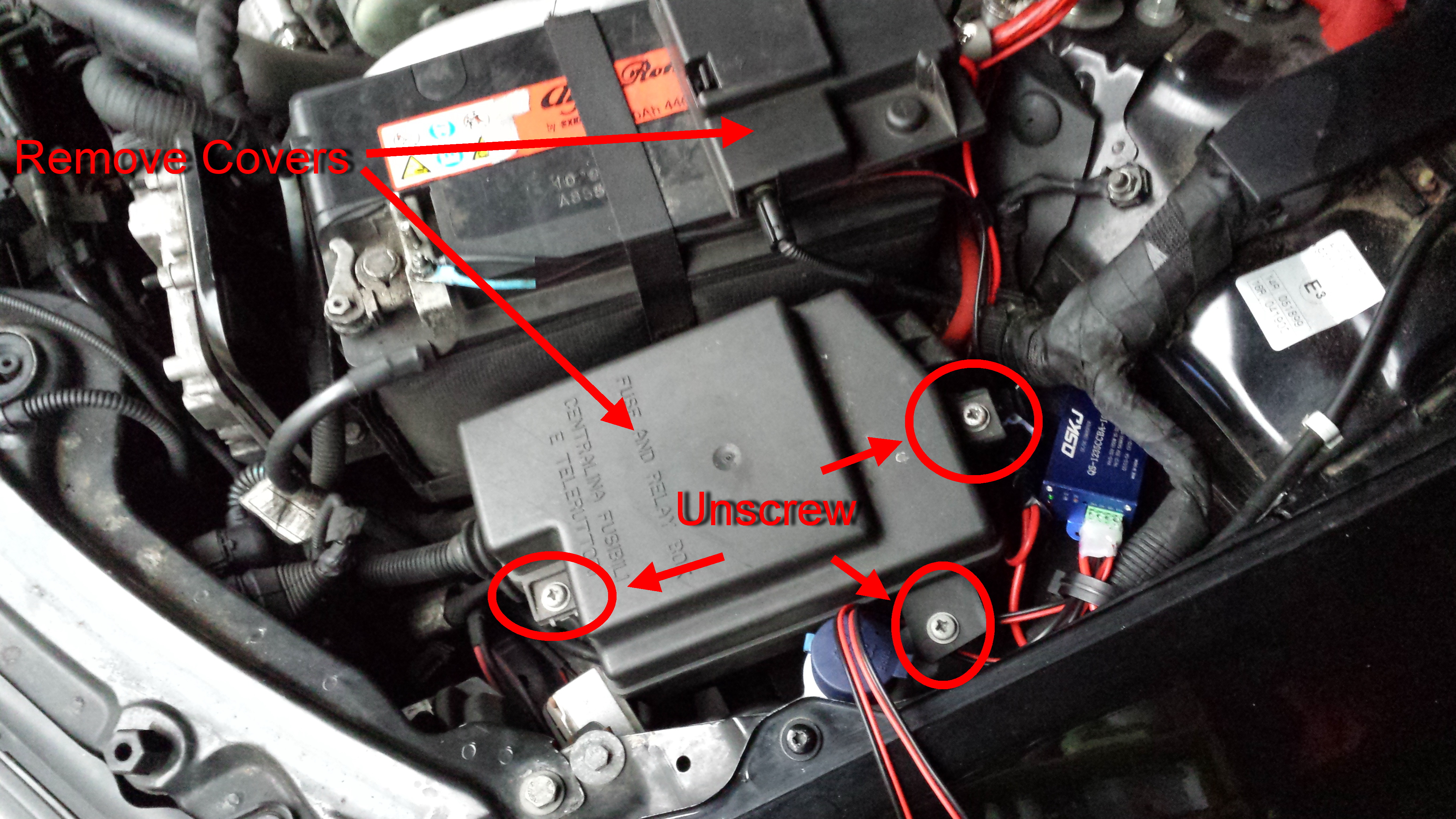
Figure 2:
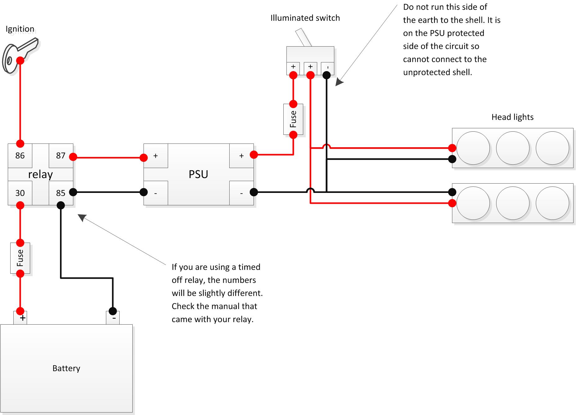
Standard Relay Diagram:
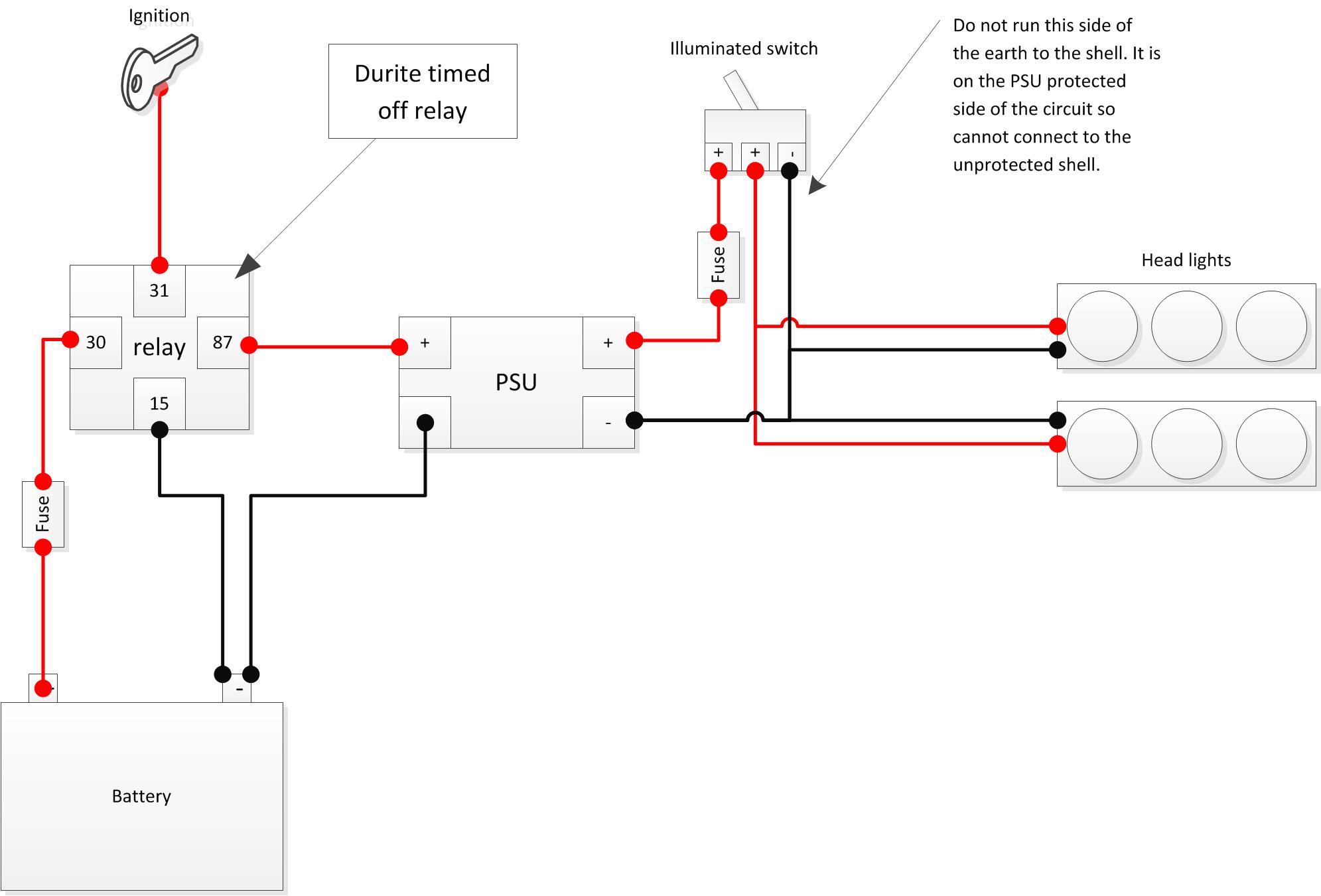
Durite Timed Off relay Diagram
Headlight runs
Once the power supply is in and running all that is left to do is to run the remaining cable 12v twin core 8.75A cable to each headlight location.
- Cut a length of wire long enough to reach the closest headlight and fit the 2 Pin Superseal Female connector to one end of it.
- Cut a second length of wire long enough to reach the headlight the furthest away and fit the 2 Pin Superseal Female connector to one end of it.
NB: make sure in both of the above steps you leave enough wire near the headlight to account for fitting & removal of the units.
- Strip back about 0.5″ the positive and negative of both wires at the end with no connector on.
- Twist both positive wires together
- Twist Both negative wires together
NB: At this stage it is recommended to solder these twisted connections to keep them secure and stop them working apart.
- Attach the Positive wires to the power supply terminal labelled “OUT +” (Figure 2, #4)
- Attach the Negative wires to the power supply terminal labelled “OUT -” (Figure 2, #4)
- Run the wires neatly around the engine bay, cable tying them to suitable locations en-route to keep them away from the engines moving parts.
NB: Some project members have had issues with their power supply spiking and destroying the controllers. It is therefore recommended that an in line fuse of 2A is added to each headlight run. This will protect the controllers in the event of a power surge due to a faulty PSU.
The Result
After this is done you will have a dedicated feed to the Halo controllers that is both regulated & protected, as well as switched on and off via the ignition of the vehicle. If you have chosen to use the timed off relay, this power supply will stay powered for the time you chose when you purchased the relay (10s suggested).
Tuning the voltage
The PSU unit has two small screws near the LEDs that are attached to trim pots inside the unit. Each of these adjustments lets you tune the amount of power (voltage & amps) that the supply is delivering. The Halo’s & Rings are low power units so will tax the PSU much. To that end, adjust the PSU as follows:
- Start with a multimeter and set the PSU to 10v output
- Connect it to the controller and connect the rings
- With the rings lit through the controller put a meter between +ve input to the controller and the +ve output to the ring and adjust for about 1v
- 1v should be about right (the NUD datasheet says it needs to be more than 0.7v and, thermally, less than 1.5v)
NB: You can measure the amps a system draws using a multi-meter by putting it in-line to the feed to the controllers: https://www.youtube.com/watch?v=HWA9WqSEjg8
NB: If you put too much voltage into the controllers, the electronics have a tougher job to get rid of the excess, and excess power is always turned into heat which can and will cause the controllers to fail. Way Too much input voltage will just blow the input regulator to the micro-controller and fry the board.
It is easy for me to detect if the controllers have failed this way and refunds will not be given!