Introduction
The goal of the wiring is to create a positive (+) and negative (-) feed from each of the following bulb feeds inside the headlight unit:
- Main Beam
- Driving Lights
- Indicator
The only bulb feed not used is the sidelight feed. This is so that you can turn on your sidelights at dusk and not alter the intensity of the Halo rings, keeping them at the daylight level.
Important Notes
- Try and make your joins as small and as neat as possible
- Where possible keep all cables routed away from the lights
- Do not let cables foul the reflector housing or the motors will strip there gears trying to adjust the beam angle!
Wiring
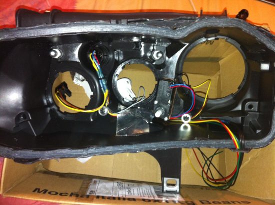
First create a 3 into 1 cable for the earth. Each feed to the controller is a + & – pair so splitting a single common earth into the 3 feeds needed for the controller inputs is fine. Once you have your earth cable, cut the black earth cable coming from the junction area in the light. This will be the cable that already has a split into a number of earths for the bulbs. Join the new earth splitter cable and route the earths through the headlight and through a hole in the bottom of the headlight case above where the controller box will be located underneath. Now cut into the coloured wire for each of the bulb feeds and join a length of wire to be routed along the same path as the earths. Colour coding these wires can be useful later on in identifying which input is which. Alternatively, consider labelling the wires.
[Not a valid template]Once you have completed the 3 feeds you will have something like this:
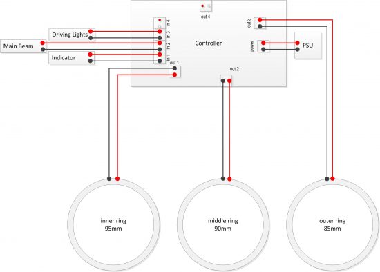
Controller Wiring Digram – V2.1 Controllers (Green)
The following image is a simplified wiring diagram for the V2.1 Controllers easily identifiable as having a green circuit board. Each of the wires you create in the above steps are connected onto the controller like this:
There should be 6 new pairs of wires from the headlight. Positive & Negative feeds from:
- Indicator
- Main Beam
- Driving Lights
Positive and negative feeds to:
- Inner ring
- Middle ring
- Outer ring
Please leave enough wire on these 6 feeds to locate the controller where you would like.
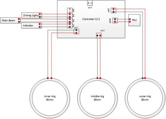
Controller Wiring Digram – V2.2 Controllers (Black)
There are differences in connections between v2.1 & v2.2 due to revisions of the board requiring a fresh routing of positive and negative tracks. This means that the polarity is the different on the V-IN (Power input from PSU) the connector handing is also reversed. Please therefore take care when wiring up your connectors to ensure that the positive is in the correct side of the connector as per the diagram.
This issue will be most apparent if upgrading from a V2.1 controller to V2.2


